Greenhouse construction tutorial. How to JDPShack. Directions part 2.
John Pandrea
ALWAYS WEAR SAFETY GLASSES, EAR PROTECTION, WORK GLOVES WHEN HANDLING METEL AND A DUST MASK WHEN DIGGING HOLES, MIXING CEMENT OR CUTTING MATERIAL.
Construction directions continued……..
Steps 51-100
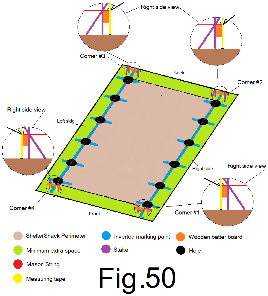
51) Measure from the ground up to the top of each batter board at all four corners to determine which corner, (ground) is the highest in elevation, (the smallest reading from the ground to the batter board is the high ground). If the building sight is relatively level, skip this step. For this tutorial, we will assume the right front corner is highest. Fig 50
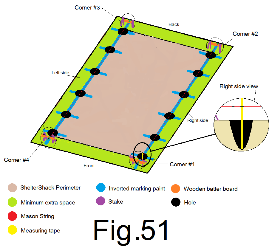
52) At the highest corner, or the right front corner, measure from the bottom of the (4 in. offset) corner hole, straight up to the string, then subtract 6 inches and make a note of this number, (write it down somewhere FRH=____). Fig 51
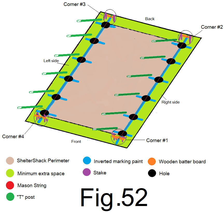
53) Place a “T” post on the ground near each of your 12 holes, on the side of the string opposite the 1 in. offset, (place inside on the right side, place outside on the left side), and, orient the “T” post bottoms toward the corresponding holes, with the flat side of the “T” post down on the right side, flat side up on the left side. Fig 52
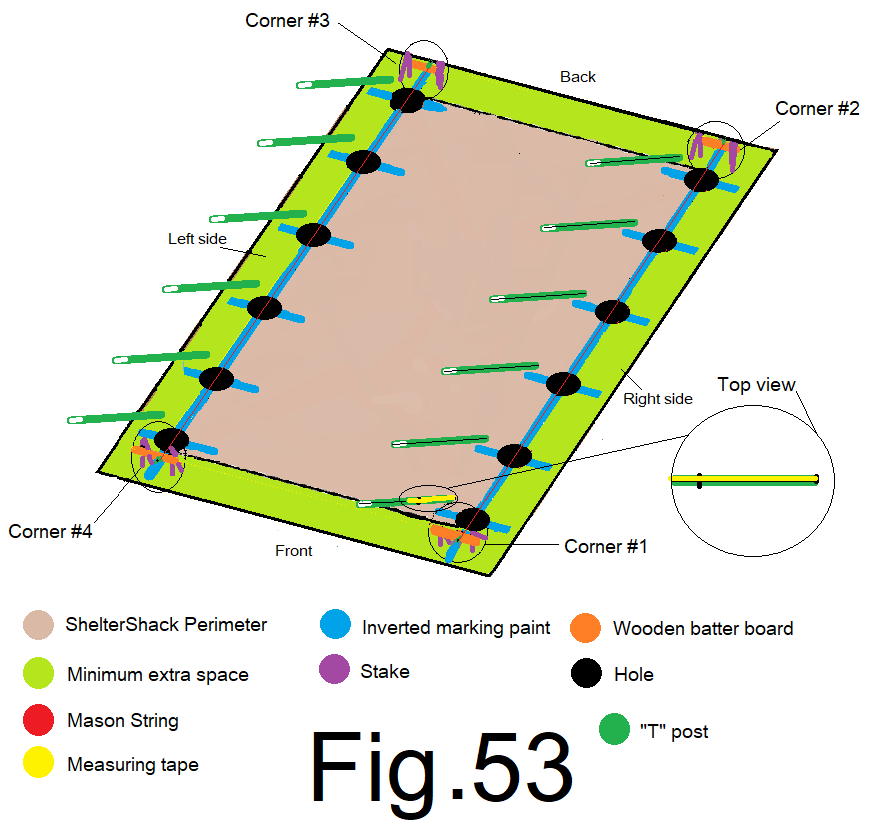
54) At the “T” post at the high corner or front right corner, measure, the distance determined in step 52) from the bottom of the “T” post, toward the top of the “T” post. Mark the “T” post on the upward edge. Fig 53
55) Measure from the top of that same “T” post from step 54), towards the bottom of the “T” post to the mark you made and make a note of that number, (write it down somewhere, T=___). Fig 54
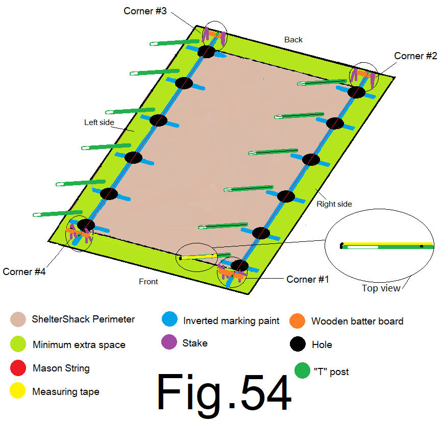
56) Use the number from step 55). Measure from the top of each “T” post, toward the bottom of each “T” post, making a mark on each post. Mark the upward edge of the “T” post on the right side, and center of the upward flat of the “T” post on the left side. Fig 55
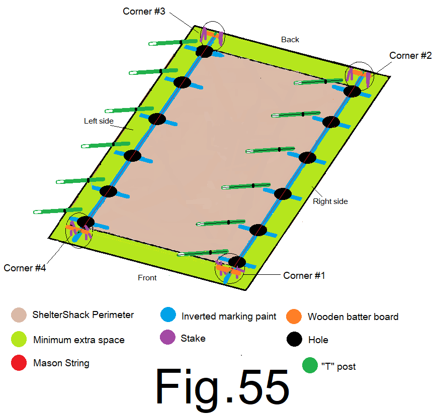
57) Mix up about 24 cubic feet of standard cement mix. If you have a cement mixer use the 3 parts #3 gravel, 2 parts #4 sand and 1 part Portland type cement formula…. Mix up the dry ingredients, add water as needed to batch up cement mix and fill your holes. Be careful; don’t get cement on the mason string. Fig 56
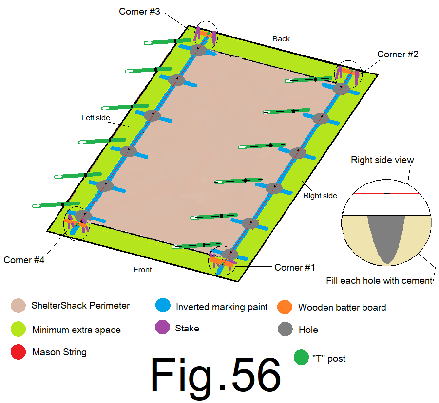
58) Starting at the front right corner, and from the inside, (on the right side), hold the “T” post by the top, with the mark on the edge side of the “T” post facing the string and with a “post level” attached to the “T” post. Lower the “T” post directly into the center of the cement filled hole keeping the “T” post plumb, (post level) and approximately ¼ inch from and directly in line with the mark on the string as you lower the “T” post about 18 inches into the cement until the mark on the edge of the “T” post lines up with the mark on the string. Fig 57
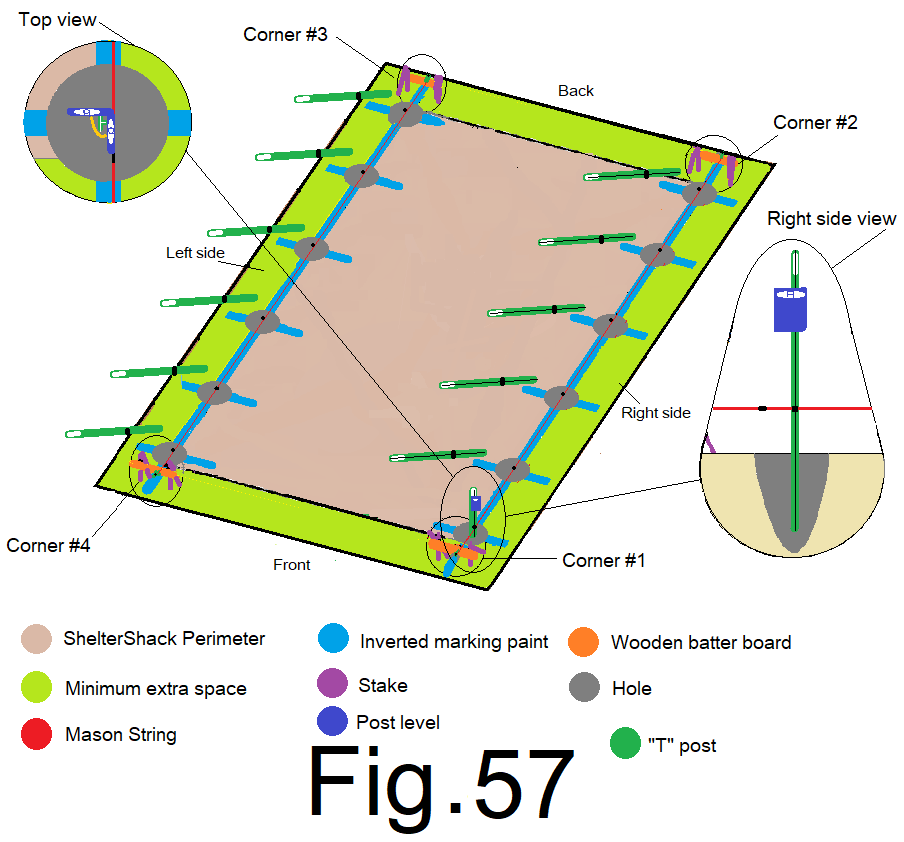
59) Repeat step 58) at the remaining 11 “T” post’s. Set the remaining 5) “T” posts on the right side wall from the inside, edge side with the mark to the string. And set the 6) “T” posts on the left side wall from the outside, flat side with the mark oriented towards the string. Fig 58
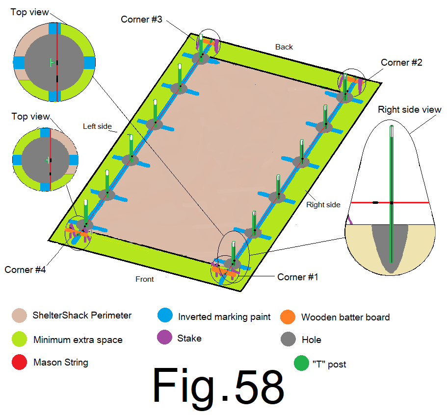
Filling your “T” post holes with cement and then setting your “T” post’s is a time sensitive process. It is best to mix up your cement and fill all of your holes and then set the “T” posts. Plan and prepare so there is no delay once you get started. Set the “T” post’s into the cement when the cement is fresh. If the cement does not support the “T” post, that’s OK, let the “T”post settle, don’t let it touch the string, and move on to the next. Keep checking back, readjusting, (don’t let anything touch the string). And, the “T” posts must be set into the cement prior to the cement setting up. If you find that mixing and pouring cement takes more time than planned, you can set “T” posts as you go. Don’t let anything touch the string!!!
You can mix your cement by hand with a garden hoe or spade shovel and a wheelbarrow. Mix 3 shovels of “#3 gravel”, 2 shovels of “#4 sand” and 1 shovel of “Portland type cement”. Mix it together dry and then add water as needed to make cement mix. This method requires a lot of work. A LOT OF WORK.
Recheck each “T” post and adjust if needed, every five to fifteen minutes, over and over, until all your “T” posts are set, plumb, and with the mark on the ”T” post lined up with the mark on the string, and with a ¼ inch gap between each “T” post and the string, and each “T” post is set and will not move.
Let the posts set in concrete for 24 hours. Remove string and dismantle and remove the batter boards and stakes. Now, time to frame your roof out of 1 in. PVC pipe, 1” PVC pipe couplings, primer and glue, and carriage bolts, washers and nuts.
60) Lay 10 sets of two 10ft. pieces of 1 in. PVC pipe on the ground end to end. Connect with 10, 1 in. PVC pipe couplings with primer and glue. Fig 59
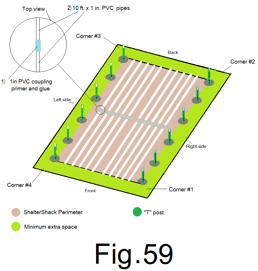
61) Measure each glued pipe to make sure they are all at least 20 ft. or longer and then cut all pipes at 20 ft. Fig 60
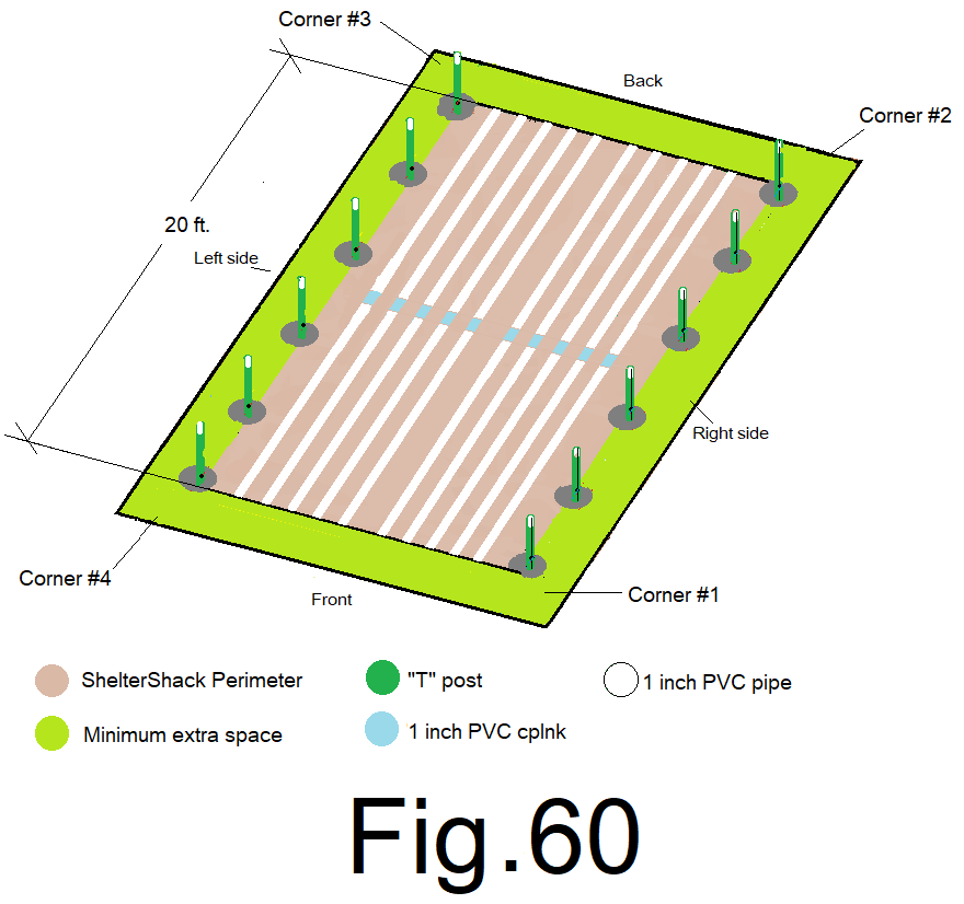
Six of the PVC pipes will become JDPShack’s arch rafters and 4 of the PVC pipes will become JDPShacks purlins.
62) Make sure all of the freshly glued rafter pipes and purlin pipes are laid out straight and on a flat surface. Use your chalk line and mark a straight line from end to end on the top of each pipe. Fig 61
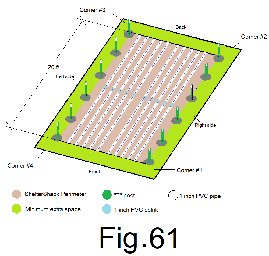
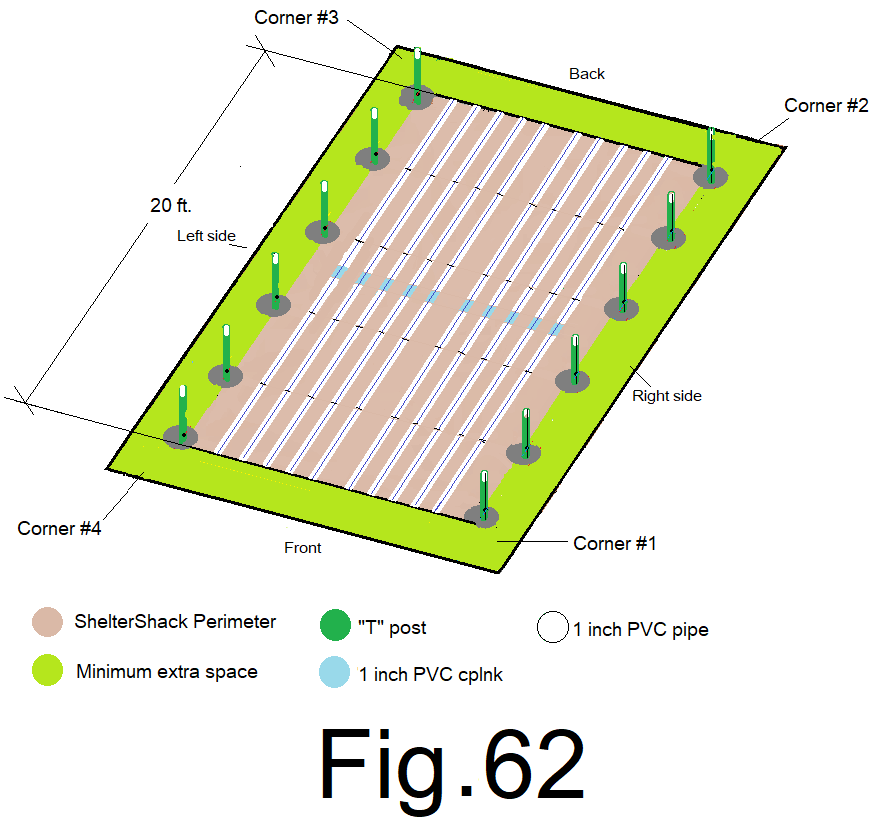
63) Start at the same end of all of the pipes, measure and cross mark, (sharpie, ink pen) the pipe at the chalk line every 4 ft. along each PVC pipe. Fig 62
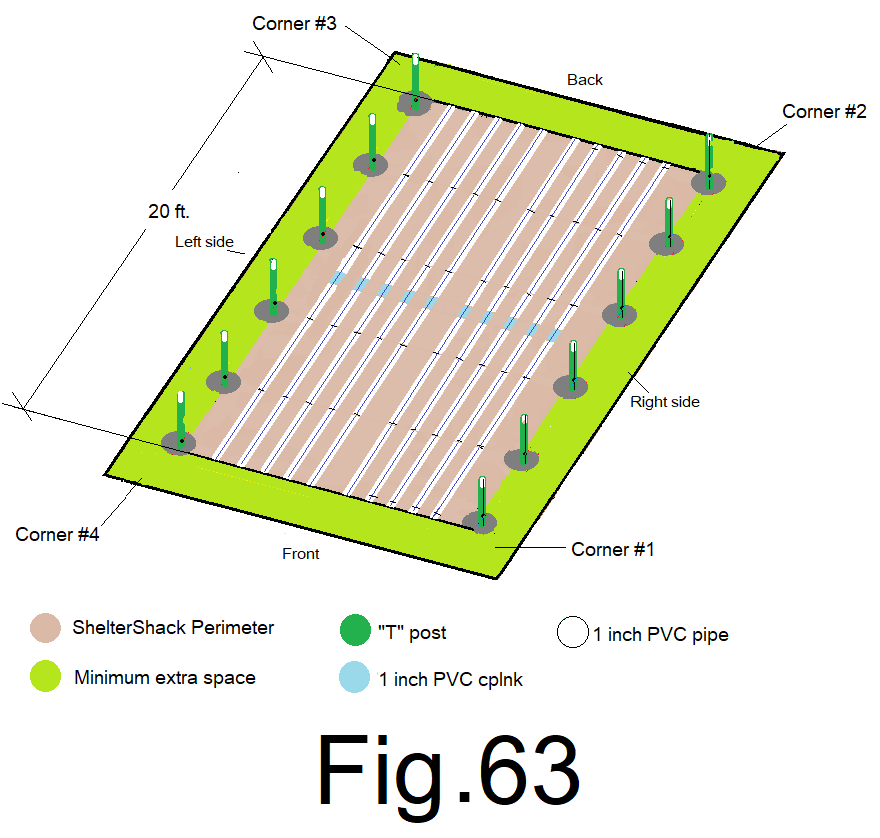
64) Measure and cross mark across the chalk line at 4 inches in from both ends of the four PVC purlin pipes only. Fig 63
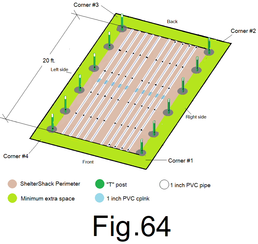
65) Use a drill with a ¼ inch bit and drill straight through the center of the PVC pipe at every mark on all rafter pipes and all purlin pipes. Fig 64
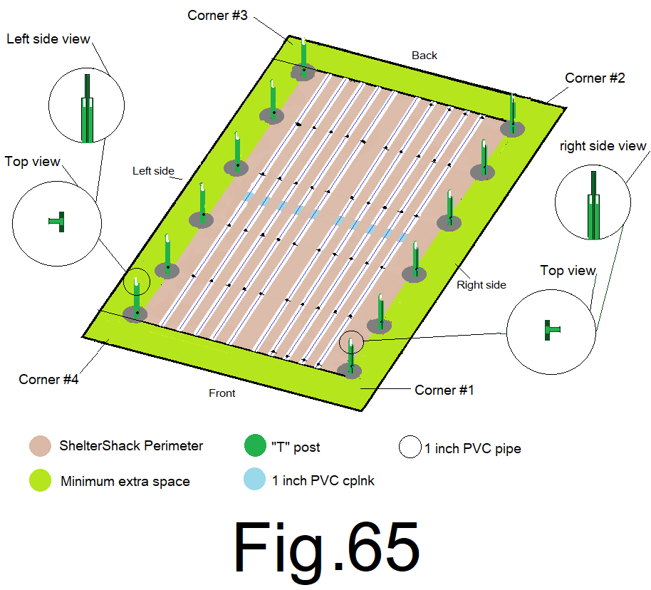
66) Use a hand held grinder with a cutting disc or a “saws all” reciprocating saw with a metal blade. Cut a 4 inch long by3/8 in. wide notch out of the back edge and front edge of the top of each “T” post. Fig 65
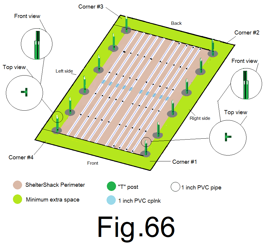
67) Use a hand held grinder with a cutting disc or a “saws all” reciprocating saw with a metal blade. Cut a 4 inch long by3/8 in. wide notch out of the outside edge of the top of each “T” post. Fig 66
For this next step you could use an assistant.
68) Pick up an arch rafter pipe by the ends with your assistant. Orient the rafter pipe into an arch shape with the drilled holes facing straight down or “in” and the opposite holes straight up or “out”. Slide one end of the rafter pipe over the top of the back right corner “T” posts down to the bottom of the notches, and then slide the other end over the back left corner “T” post down to the bottom of the notches. Fig 67
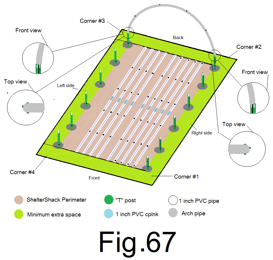
The arch rafter should sit stable, over the top of the “T” post’s.
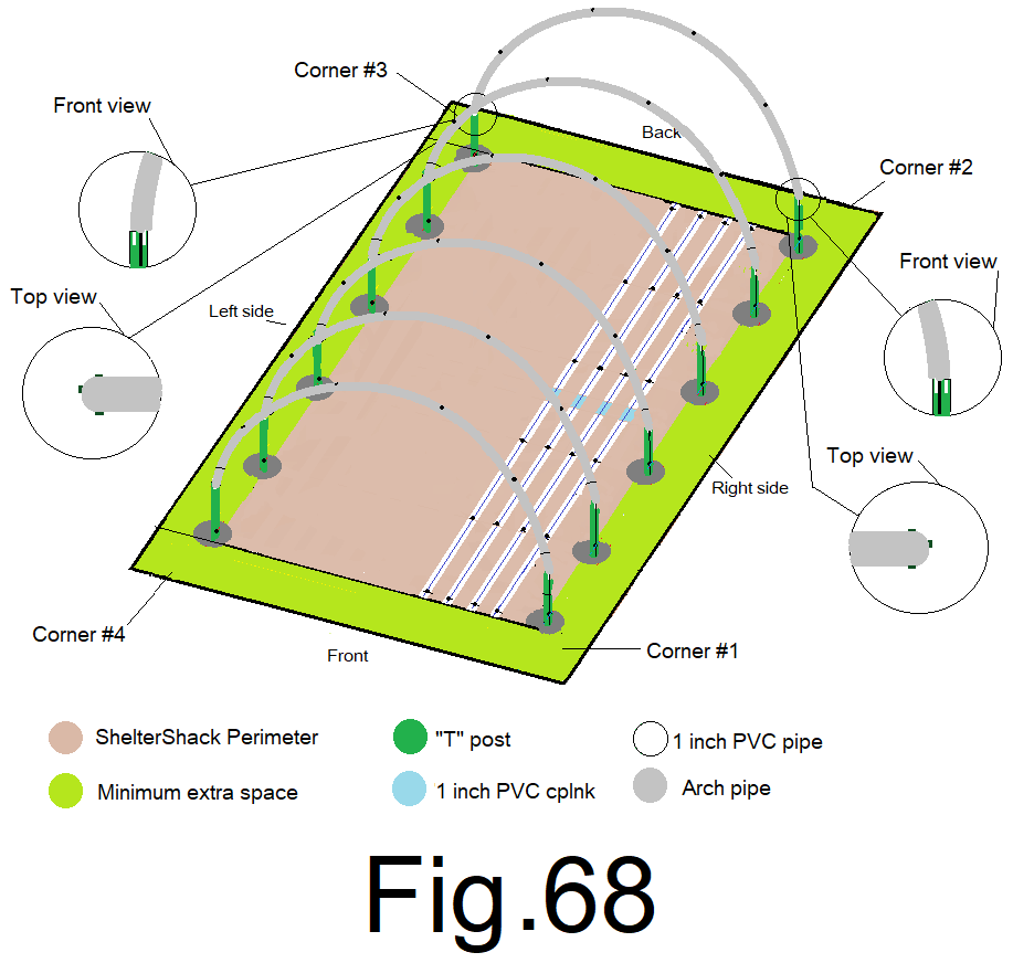
69) repeat step 68), continuing from the back, working toward the front at the remaining 5 arch rafter locations, remember to orient the arch rafter’s holes straight down or “in” and straight up or “out” as you set the rafters. And make sure the arch rafter pipes sit all the way down on the “T” post. Fig 68
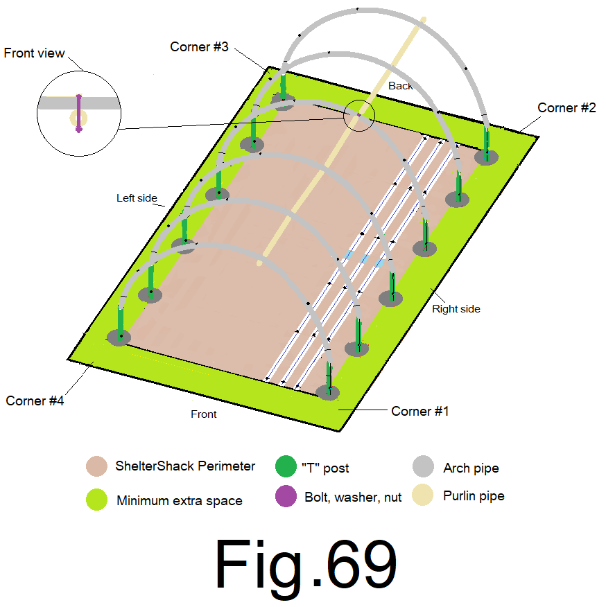
70) Using a step ladder, attach 1 upper purlin pipe to the bottom of 1 middle arch rafter pipe. Use a 3/8” x 3” carriage bolt from the top down through the arch rafter, the purlin, the lock washer and finger tighten the nut, do not wrench tighten for now… Fig 69
71) Attach the purlin pipe to the remaining arch rafter pipes using the carriage bolts, lock washers and nuts. finger tighten only for now. Fig 70
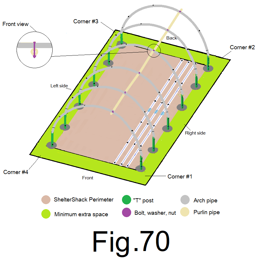
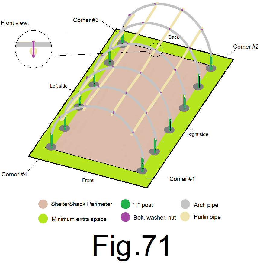
72) Attach the remaining 3 purlin pipes to the arch rafter pipes repeating steps 70) and 71) loosely finger tighten the bottom nuts for now. Fig 71
***Spread out your “fairly straight” 20 ft. 2x4s and find the two that have the least amount of stiffness. You can do this by holding the 2×4 off the ground at one end. Move it in an up and down motion, noting the “flex” at the middle of each. Pick the 2 with the most flex and set them aside.
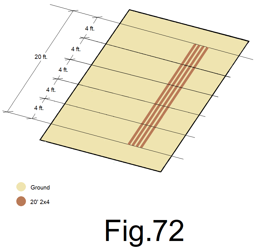
73) Place four 20 ft. 2×4’s on the ground. Measure from the same end on each 2×4 and mark the 2×4 every 4 ft. all the way to 20 ft., and then cut all four 2x4s at 20 ft.. Fig 72
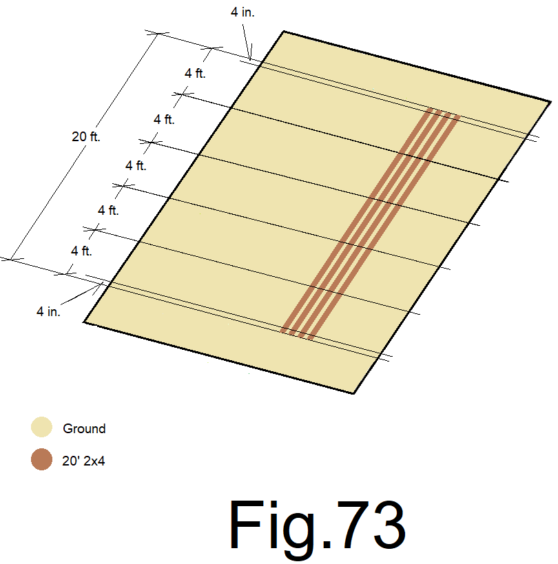
74) Measure and mark at 4 in. in from the ends, at both ends, on all four 2×4’s, Fig 73
75) Use your “speed square” and make a cross mark on every 2×4 at every mark. Fig 74
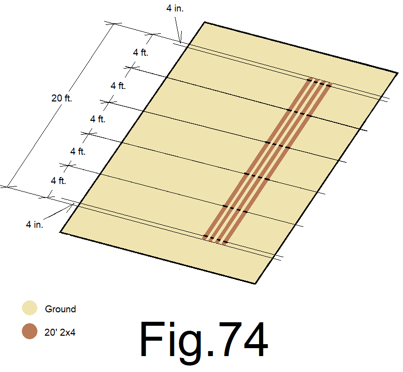
76) Use your “skill saw” and cut a ¾ in. deep “kerf cut” on both sides of each line on each 2×4, leaving an 1/8 in. of material including the line between the two “kerf cuts”. Fig 75
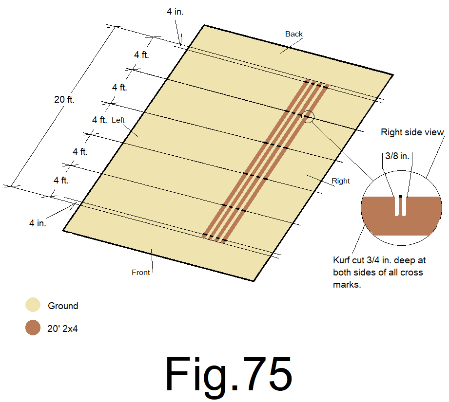
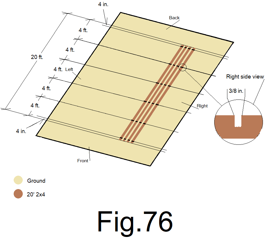
77) Use a wood chisel and clean the 1/8 in. of material between the kerf cuts at all cross marks on all 2×4’s. Fig 76
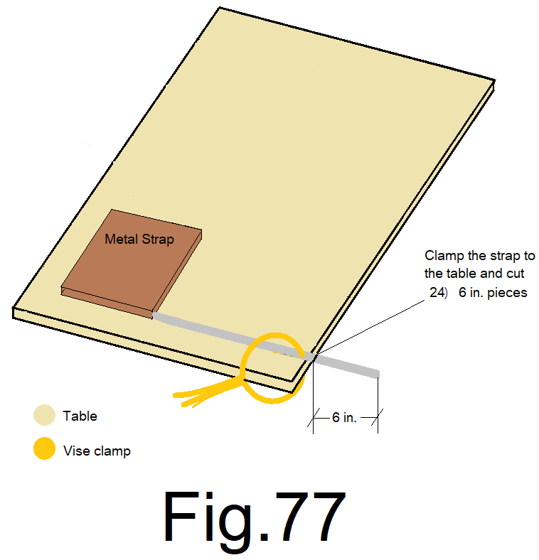
78) Using the “Simpson strong tie”1 in. metal strapping, clamp the end of the strapping to a table leaving just over six inches over hang. cut the strapping, adjust and cut again and again, into (24) 6 inch pieces with your “sawsall” reciprocating saw. Fig. 77
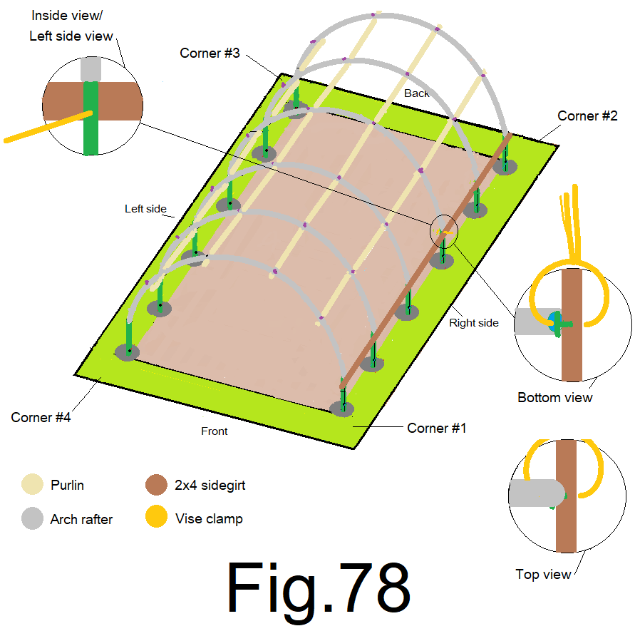
79) Place one kerf cut 20 ft. 2×4 against the outside top of the right sidewall back middle “T” post. Line up the kerf cut slot on the 2×4 girt to the top of the corresponding right side wall back middle “T” post outside edge. Slide the kurf slot over the “T” post edge with the top edge of the 2×4 girt edge against the bottom of the arch rafter pipe, (arches should be down tight on the “T”post tops). Use a “vise grip” “C” clamp to clamp the 2×4 girt to the “T” post. Fig 78
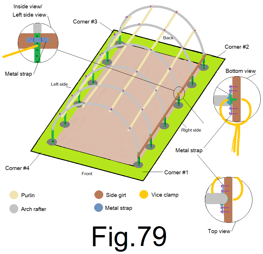
80) Use a screw gun, 1 in. wood screws and a 6 in. metal strap to attach the 2×4 to the “T” post. Fig 79
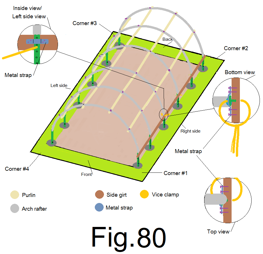
81) Remove the clamp and clamp the 2×4 girt to the front middle “T” post, make sure the 2×4 girt is up against the bottom of the arch rafter pipe. Use a screw gun, 1” wood screws and a 6 in. metal strap to attach the 2×4 to the “T” post. Fig 80
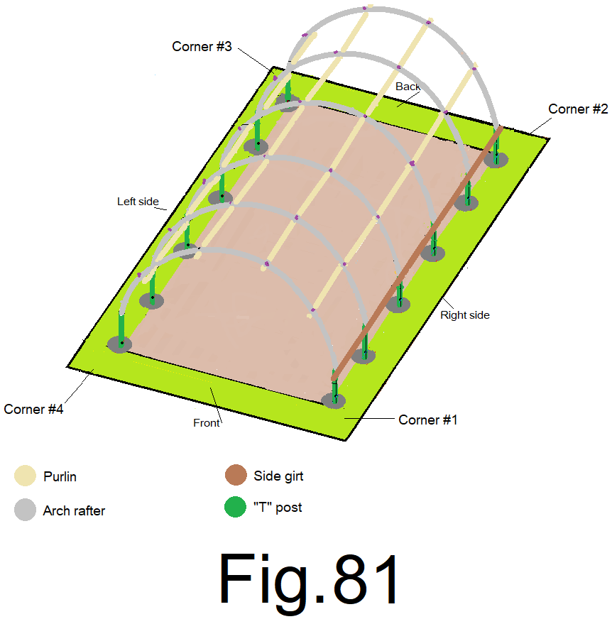
82) Repeat these steps for the remaining 2×4 girt to “T” posts connections. Fig 81
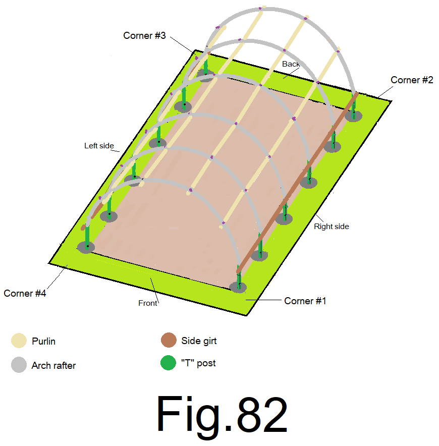
83) Repeat steps 79) through 82) on the other side of your JDPShack. Fig 82
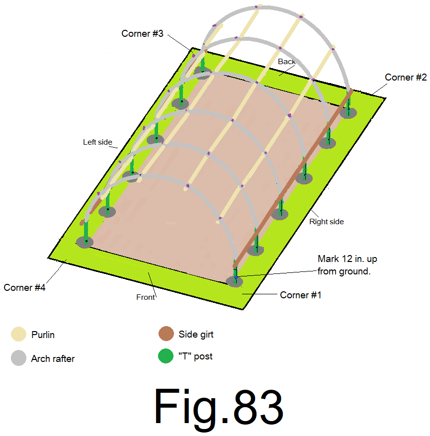
84) At the lowest corner measure up from the ground along the corner “T” post and make a mark 12 inches up. We will assume the right front corner is the lowest. Fig 83
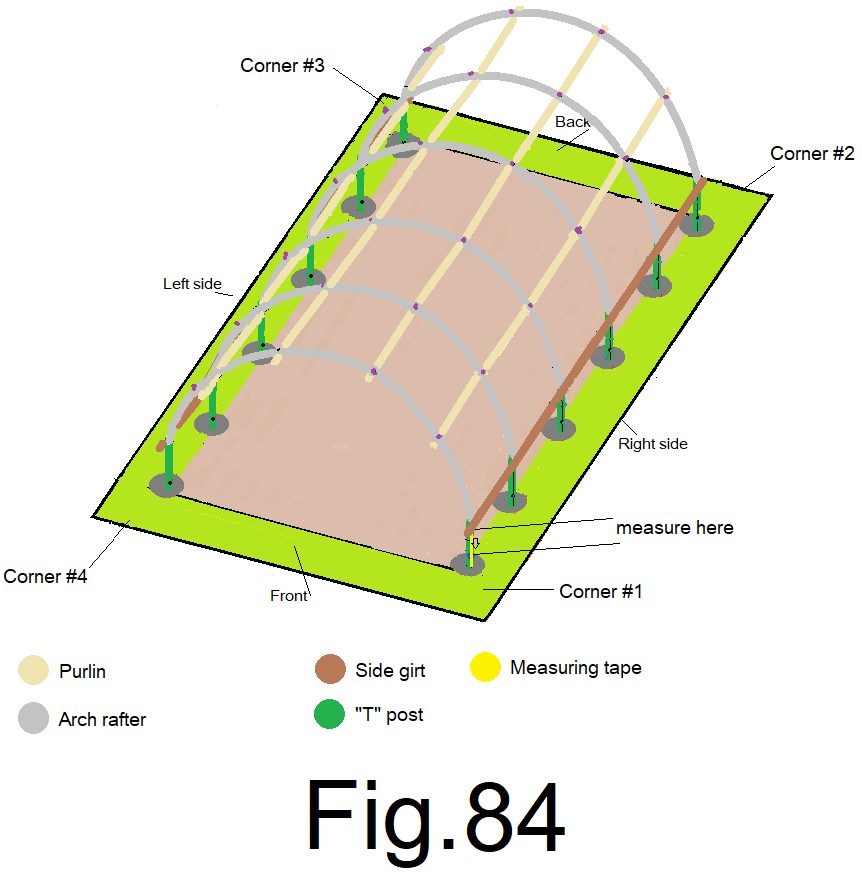
85) Measure down from the bottom of the upper 2×4 side girt and make a note of that number, (write it down somewhere F=___). Fig 84
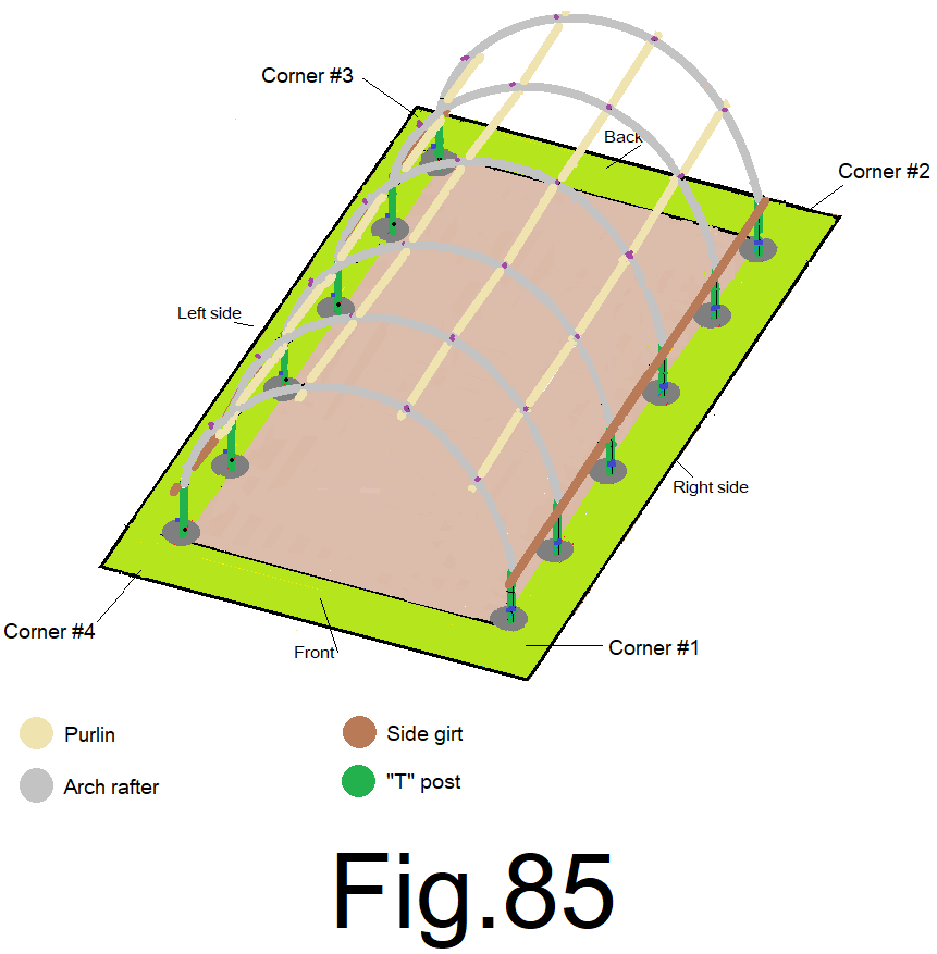
86) Using the number from step 85), at the other 11 “T” posts, one at a time, measure down from the bottom of the upper 2×4 side girt and mark the “T” post. Fig 85
87) Attach a 2×4 side girt along the bottom of the right side wall using the same method as in steps 79 through 83. Keep the top edge of the 2×4 girt in line with the mark on each of the “T” posts while attaching. Fig 86
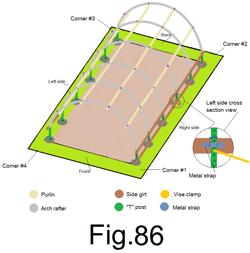
NOTE; If you find that 1 or more of the kurf cuts on the 2×4 bottom side girts don’t line up with the corresponding “T” post outside edge. Line up those that do and clamp them. Those that don’t, mark 2 lines on the inside of the 2×4 where the outside edge of the “T” post meets the 2×4, both sides of the “T” post edge and then remove the 2×4 and re- kurf the ones that need it between the 2 lines. It should be very close to the original kurfs. If you must make the existing kurf bigger, that’s OK, do it.
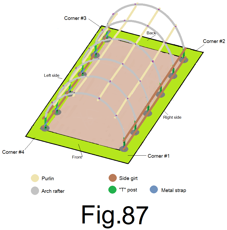
88) Repeat step 87) on the other side. Fig. 87
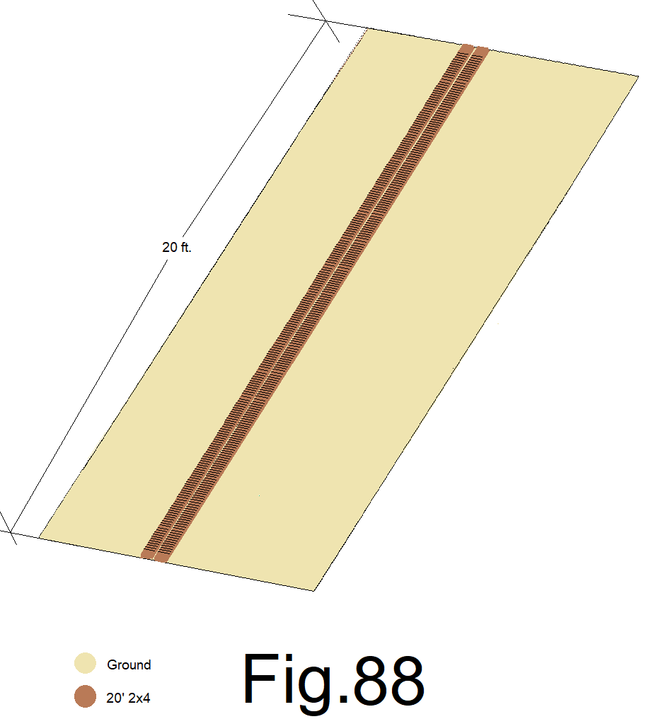
89) Place the two most flexible, (from step *** above 73)) 20 ft. 2×4’s tight together, on the flat ground. Match up the ends of both 2x4s together and measure from that end; marking both together and then cutting both together will save time. At 4 inches make a mark on both 2x4s and then make a mark at every inch all the way to the other end of the 2×4, making the last mark at 19 ft. 8 in. Then mark both 2x4s at 20ft. Using a speed square, make a cross mark on all of your marks. Fig 88
90) Using your “Skillsaw”, Cross cut both 2x4s at 20 ft., then, set your skill saw depth to 1 in. and make a 1 inch deep kerf cut at each cross mark, one inch apart. If the 2x4s want to move, set 3 stakes into the ground next to the 2x4s on one side, evenly spaced and cut the Kurfs from the other side, when you get to the stake, carefully slide both 2x4s together, to clear the stake. Fig 89
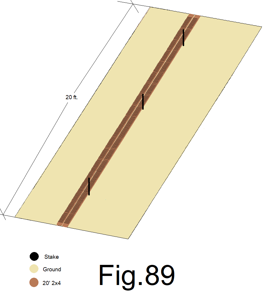
That is a lot of kerf cuts and will allow the 2x4s to flex in order to form the arch shape necessary to become “end wall caps”.
An assistant may be needed for this next step. Be careful handling your freshly kurfed end wall caps.
91) Flip a 2×4 end wall cap over, smooth side up, kerf side down. From both sides near the middle, lift the 2×4 end wall cap into position on top of the end wall purlin pipes, tight against the arch rafter pipe and centered from end to end (sight the bottom of the 2×4 arch cap at both ends where it meets the top side wall girt, both sides should be even with a small gap between the end of the arch cap and the top of the sidewall girt. You may have to trim the 2×4 end wall cap at both ends, evenly.
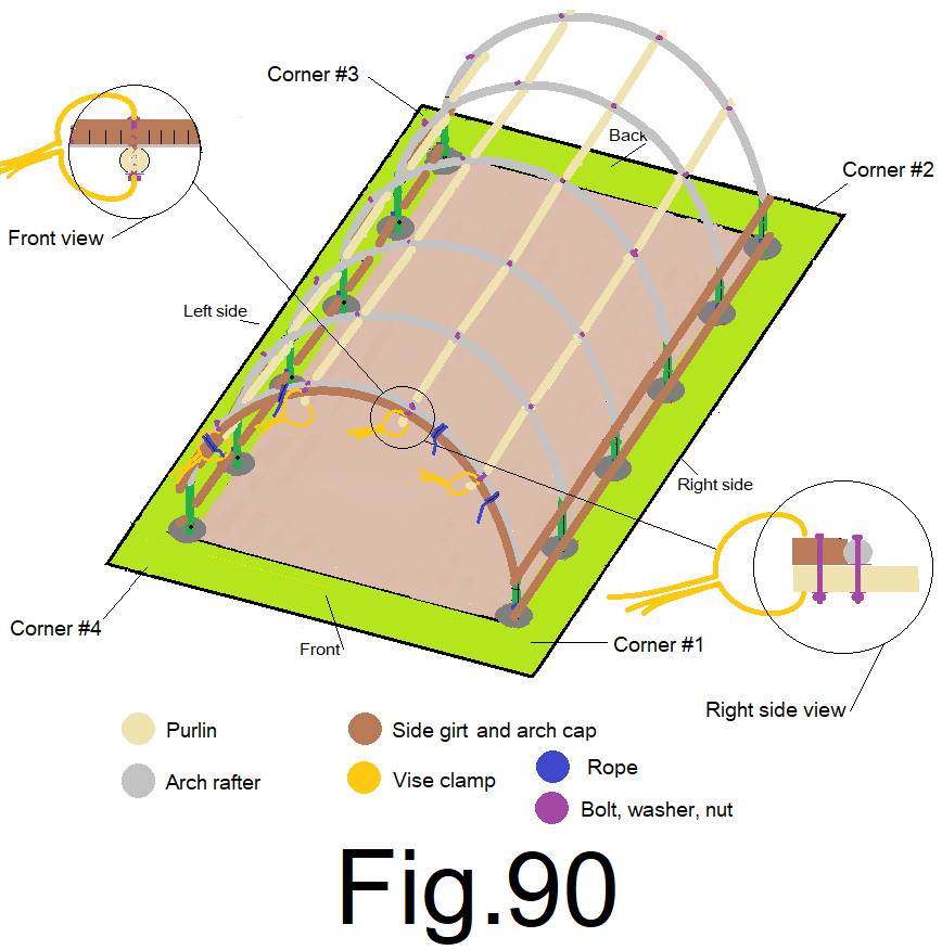
Using four 3 ft. long sections of rope. and 4 vise grip “C” clamps. Double wrap, cinch and tie the 2×4 end wall cap to the arch pipe with the ropes at four location, evenly spaced, one near each end and the other two evenly spaced on both sides of the middle. Then clamp the 2×4 end wall cap to the four purlin pipe ends, close to the outside edge of the 2×4, clamp all four. Check to make sure the end wall cap is positioned and tied tightly next to the arch pipe and clamped to each purlin pipe. This action will straighten the roof frame. Notwithstanding, leave the roof frame arch to purlin nuts loose until you complete installing the end wall cap on the other end wall.
Using a drill with a 5/16 in. drill bit, drill a hole through both the center of the end wall cap and the center of the purlin pipe all at once from the top and secure them together with a 3 in. x ¼ in. carriage bolt inserted from the top, through the 2×4 arch, the purlin pipe, the lock washer and nut at the bottom. Tighten the nut on all 4, not to tight. Remove clamps and ropes. Fig 90
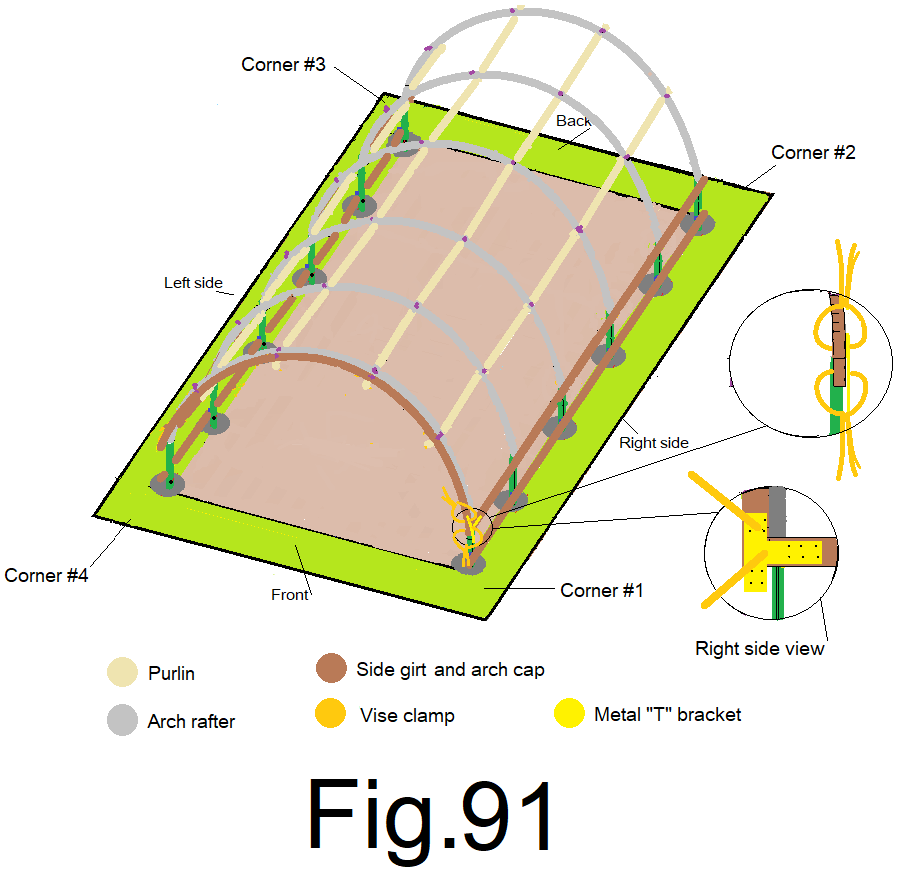
92) Using two vise grip “C” clamps, clamp one arm of the metal “T” bracket to the end of the right side of the 2×4 end wall cap and clamp the leg of the metal “T” bracket to the front end of the right sidewall girt. Fig 91
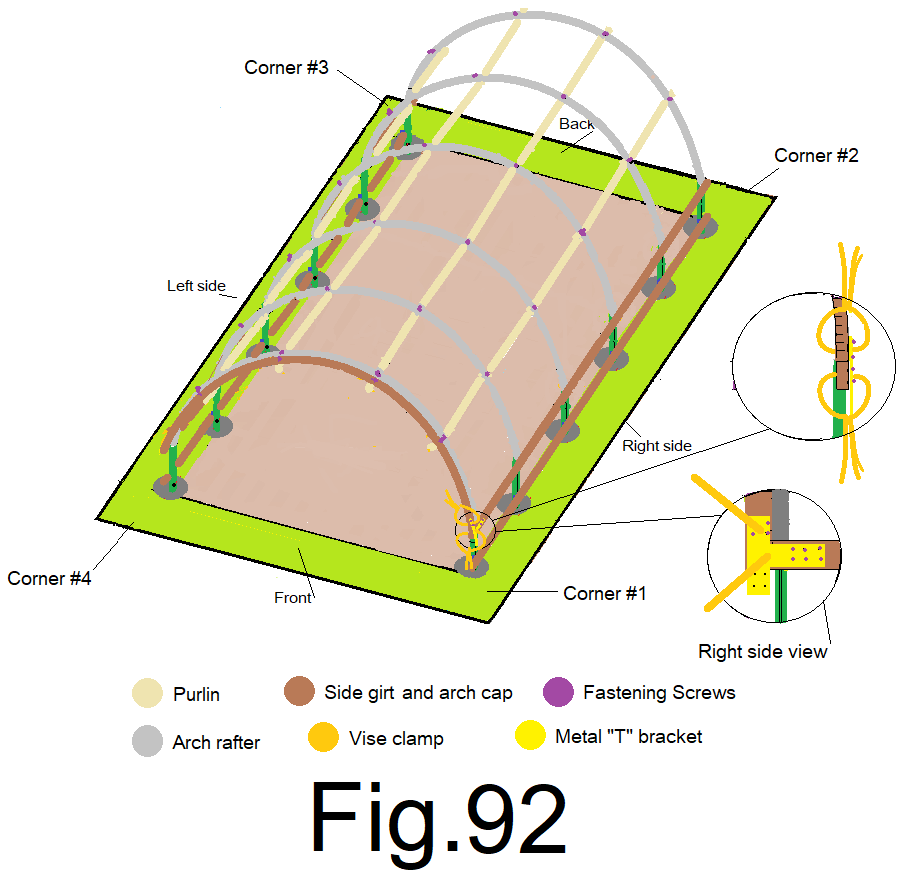
93) With 1” wood screws, secure the metal “T” bracket to the right end of the wall cap and the right side wall top girt. Fig 92
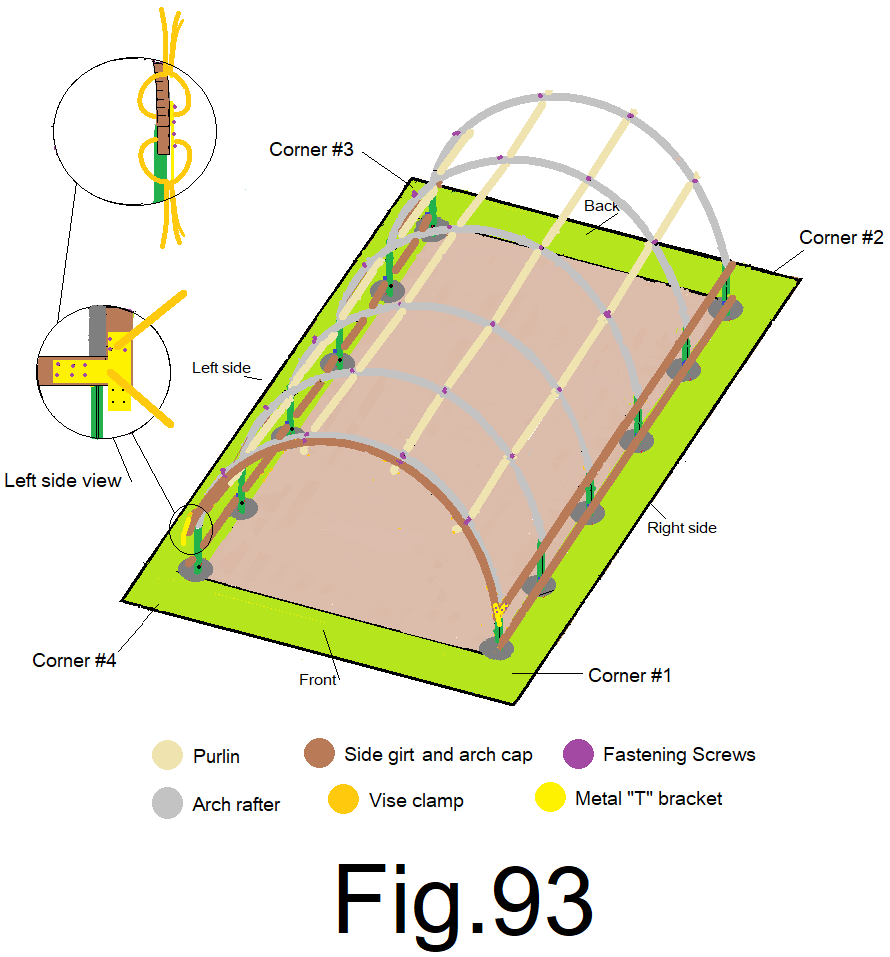
94) Repeat steps 92) and 93) at the front left sidewall at the other end of the arch. Fig 93
95) repeat steps 91) through 94) at the back end wall and then tighten all arch pipe to purlin pipe connection nuts from from step 72).
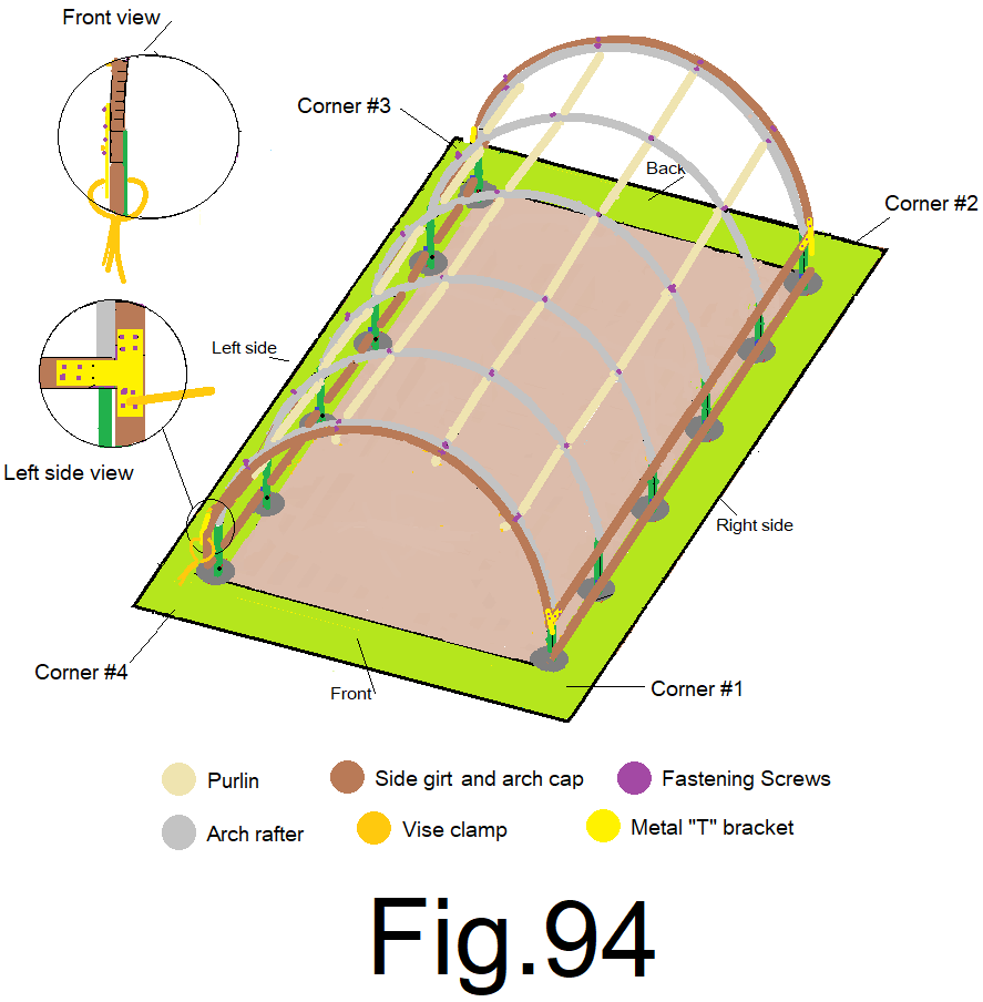
96) At the front left corner, measure between the bottom of the top left side girt and the top of the bottom left side girt. Using that number measure, mark and cut a 2×4. Install that 2×4 between the top and bottom girt at the front left corner and using a vise grip “C” clamp, clamp that 2×4 end wall insert to the metal “T” bracket at the top of the corner insert, the front outside edge of the top girt and the 2×4 insert should line up flush, attach with 1”screws and remove the clamp. Fig 94
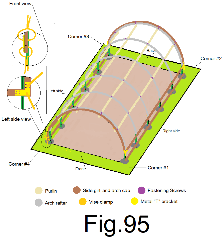
97) At the front left corner, using 2) vise grip “C” clamps, clamp a metal “L” bracket to the bottom left side girt and to the 2×4 corner insert, the front outside edge of the bottom girt and the 2×4 insert should line up flush, secure with 1”screws and remove clamp. Fig 95
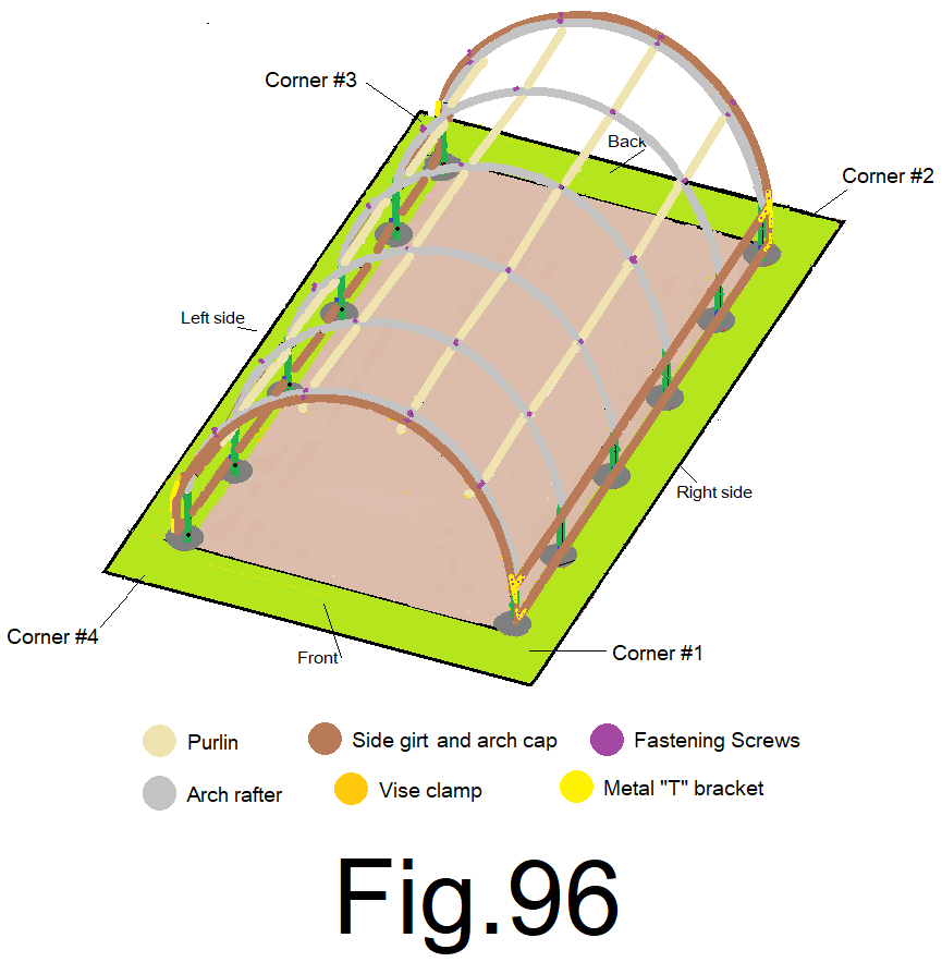
98) Repeat steps 96) and 97) at the other 3 corners. Fig 96
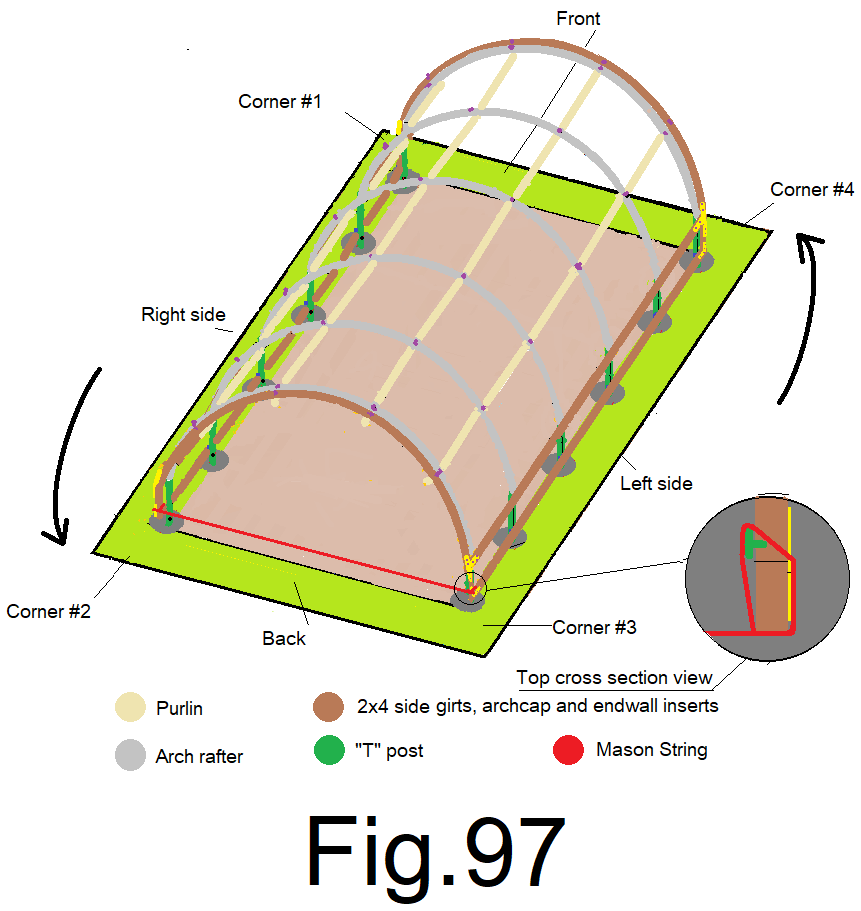
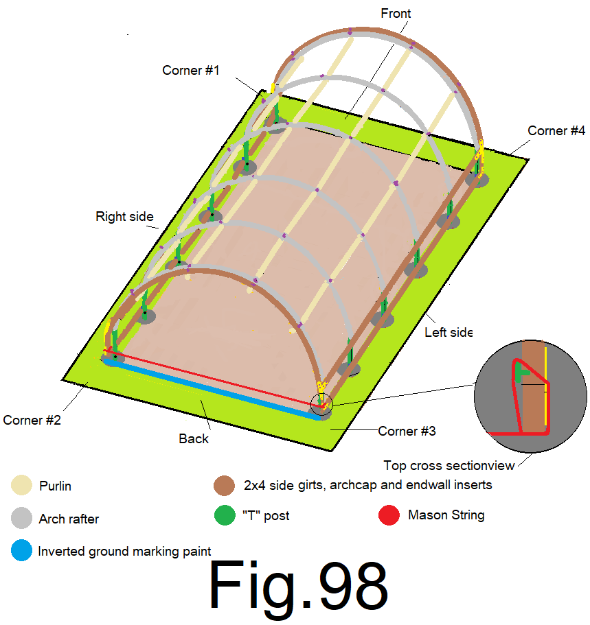
99) At the back end wall, attach a mason string to the right sidewall 2×4 corner insert, down near the bottom girt. Extend the string to and attach it to the left sidewall 2×4 corner insert, down near the bottom girt. Make sure to orient the string to the outside edge of the 2×4 corner inserts and tighten the string. Fig 97
100) Using a spray can of “inverted marking paint” mark a line on the ground, directly under the string. Fig 98
© 2021