Greenhouse construction tutorial. How to JDPShack. Directions part 5.
John Pandrea
ALWAYS WEAR SAFETY GLASSES, EAR PROTECTION, WORK GLOVES WHEN HANDLING METEL AND A DUST MASK WHEN DIGGING HOLES, MIXING CEMENT and CUTTING or DRILLING.
How to JDPShack
Steps 201-250
201) At the center of the left side wall, pull the screen straight up and staple it to the top girt while holding the screen 1 in. above the top girt. Fig 197
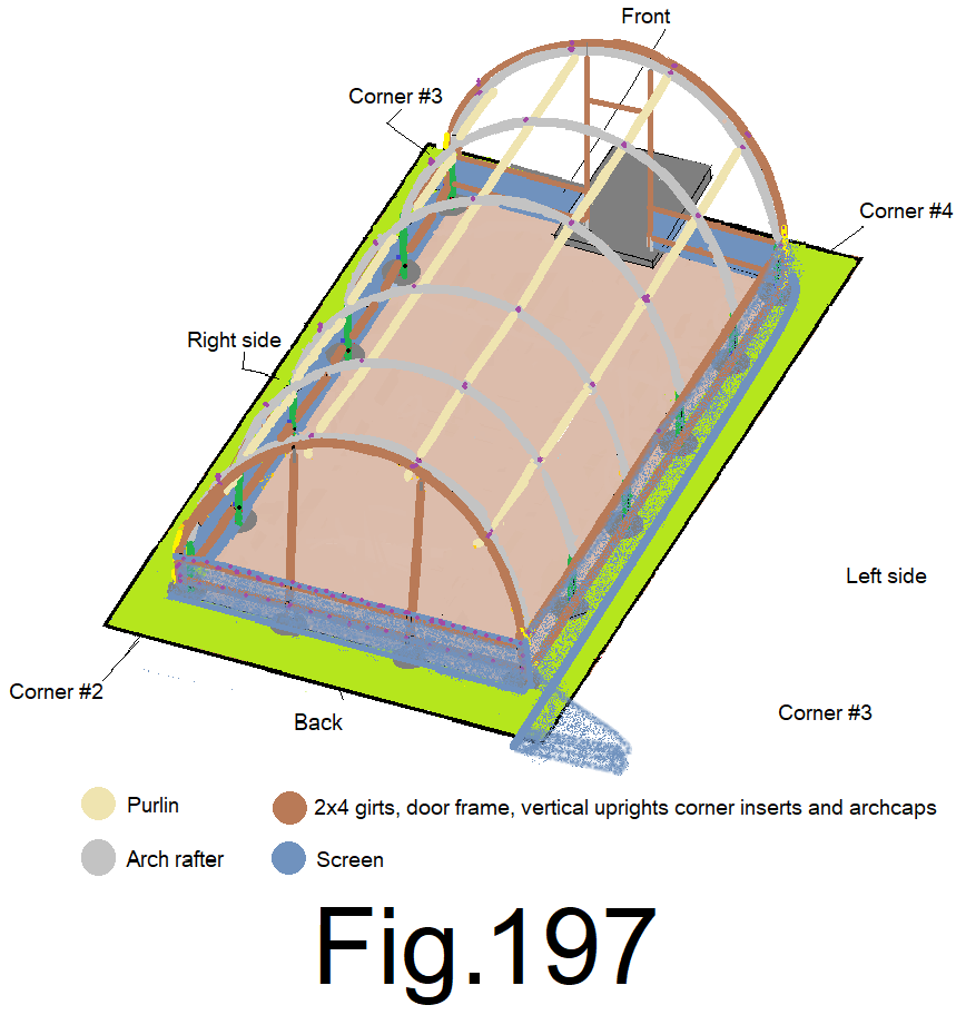
202) At the quarters of the left side wall, pull the screen straight up and staple it to the left side top girt while holding the screen 1 in. above the top girt. (2 locations) Fig 198
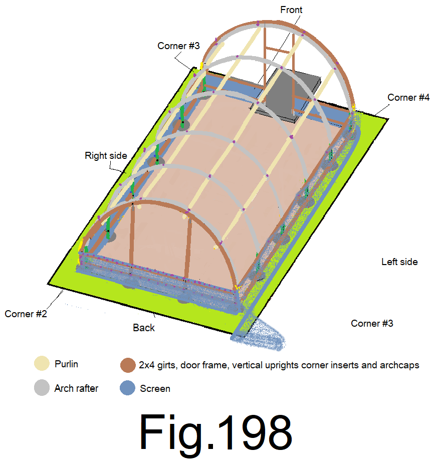
203) At the eighths of the left side wall, pull the screen straight up and staple it to the left side top girt while holding the screen 1 in. above the top girt. (4 locations) Fig199
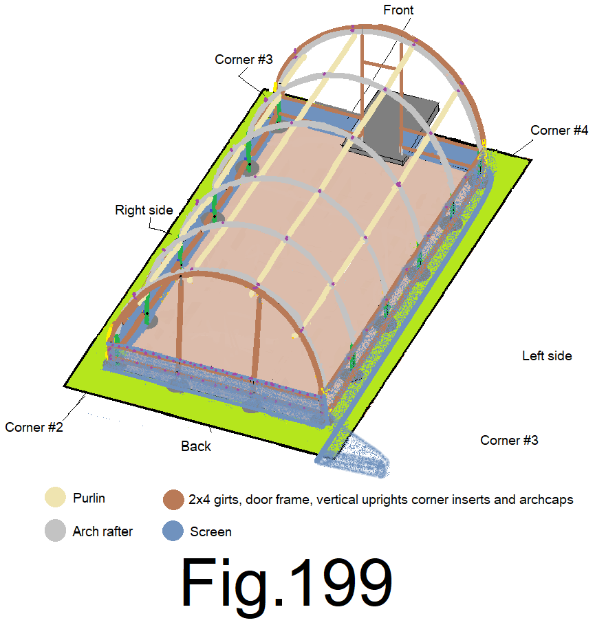
204) At the sixteenths of the left sidewall, pull the screen straight up and staple it to the left side top girt while holding the screen 1 in. above the top girt. (8 locations) Fig 200
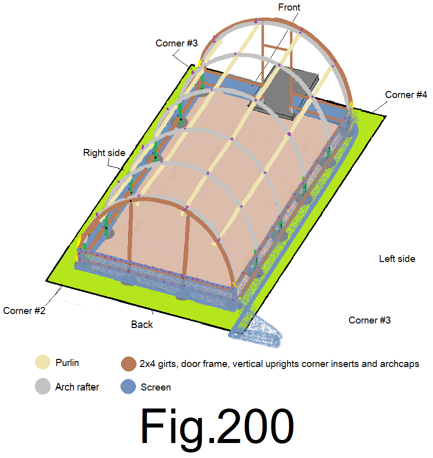
205) At the thirtyseconds of the left sidewall, pull the screen straight up and staple it to the left side top girt while holding the screen 1 in. above the top girt. (16 locations) Fig 201
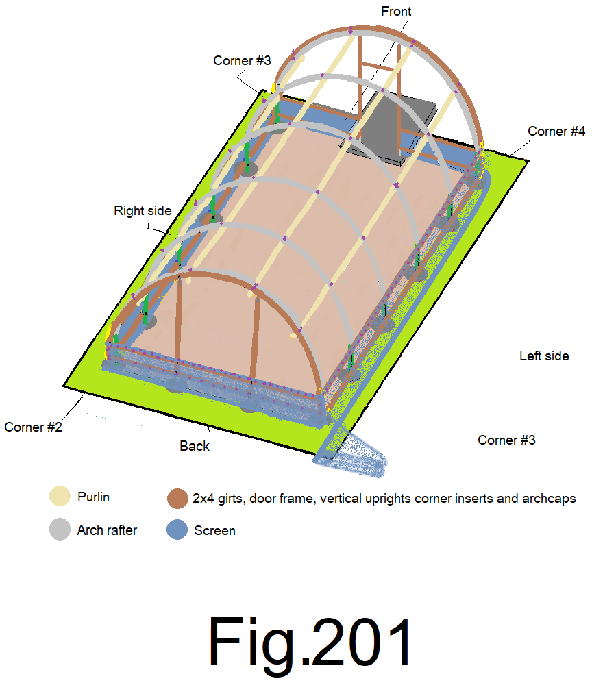
206) At the center of the left sidewall, slightly tension the screen straight down and staple it to the bottom girt. Let the extra screen fold at the ground and lay on the ground. Fig 202
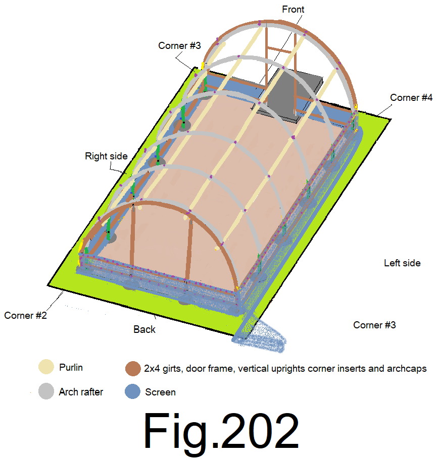
207) At the quarters of the left side wall, slightly tension the screen straight down and staple it to the bottom girt. (2 locations) Fig 203
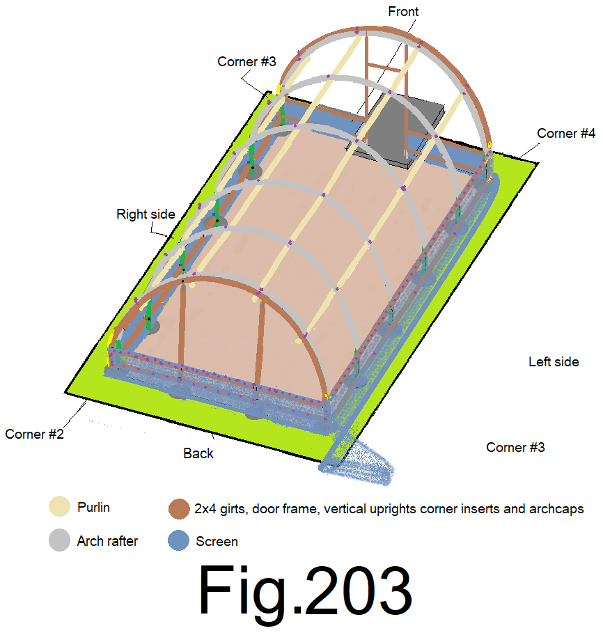
208) At the eighths of the left side wall, slightly tension the screen straight down and staple it to the bottom girt. (4 locations) Fig 204
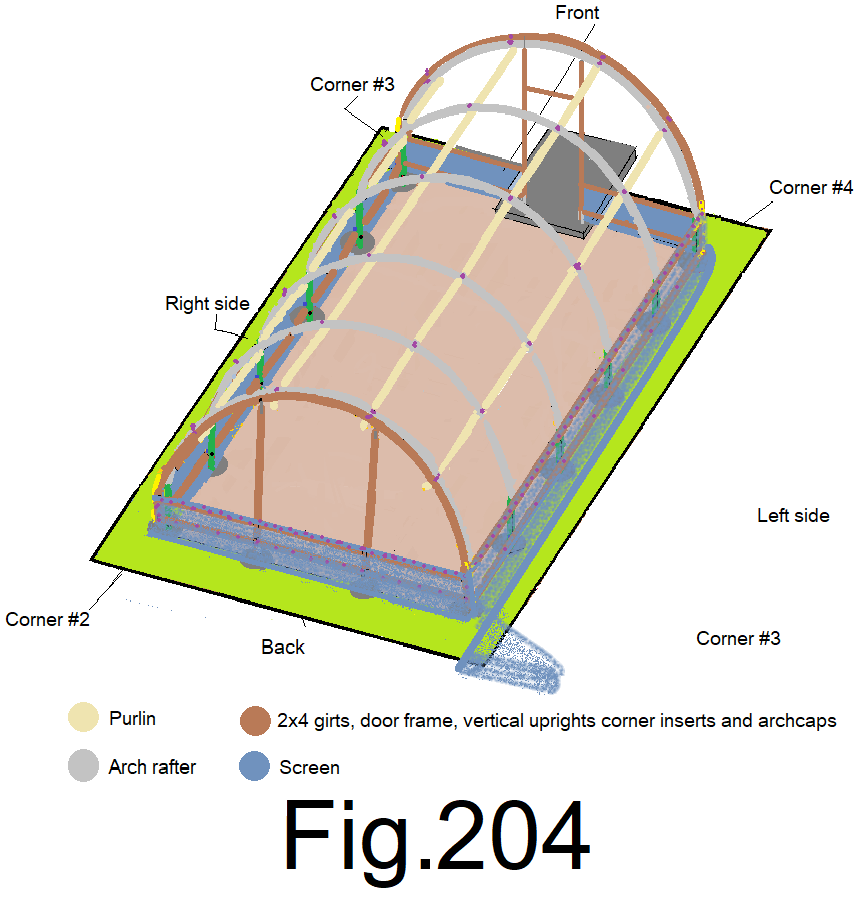
209) At the sixteenths of the left side wall, slightly tension the screen straight down and staple it to the bottom girt. (8 locations) Fig 205
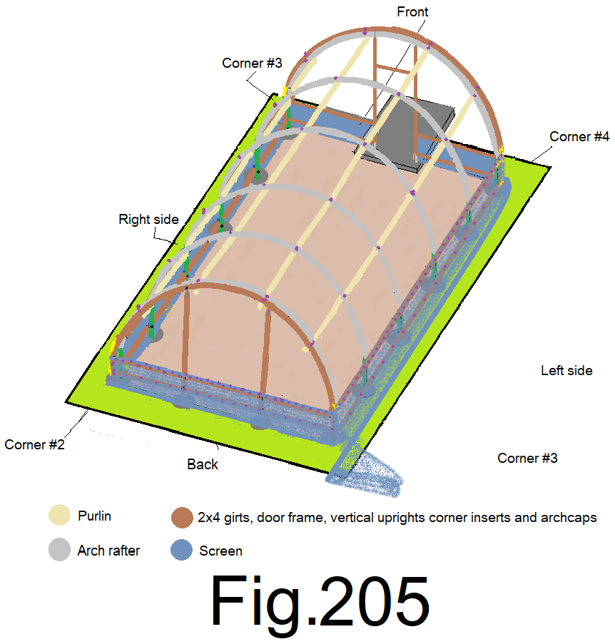
210) At the thirtyseconds of the left side wall, slightly tension the screen straight down and staple it to the bottom girt. (16 locations) Fig 206
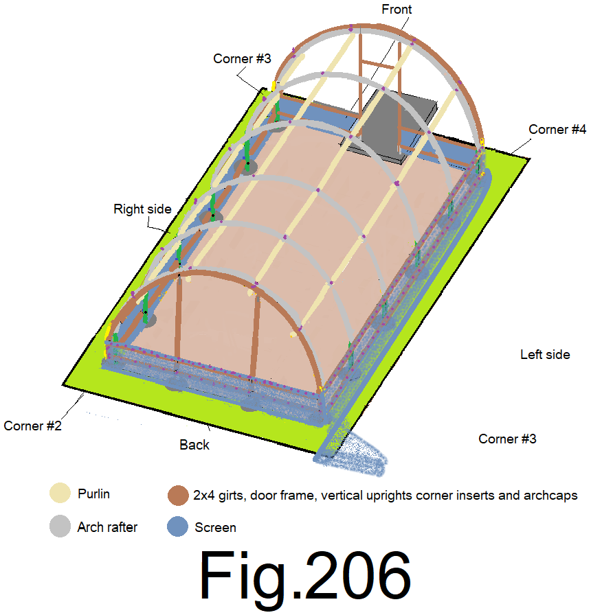
211) At the left side corners, slightly tension the screen straight down and staple it to the bottom sidewall girt. Staple the screen sides at every 4 in. along the left side front and back corner inserts. Fig 207
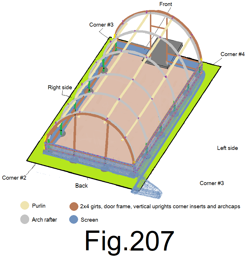
212) Cross Cut the screen 4 inches past the left back corner. Use a pair of large fabric scissors, a razor knife or (use a small electric soldering iron if the screen is woven, nylon based and subject to unraveling). Carefully cut the bug screen. Fig 208
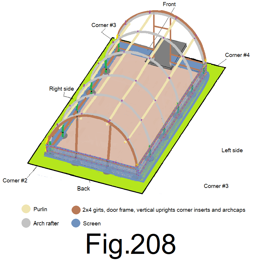
213) Cut the screen along both inside edges of the door frame and then straight out away from the building at the bottom. Use a pair of large fabric scissors, a razor knife or (use a small electric soldering iron if the screen is woven, nylon based and subject to unraveling). Carefully cut the bug screen. Fig 209
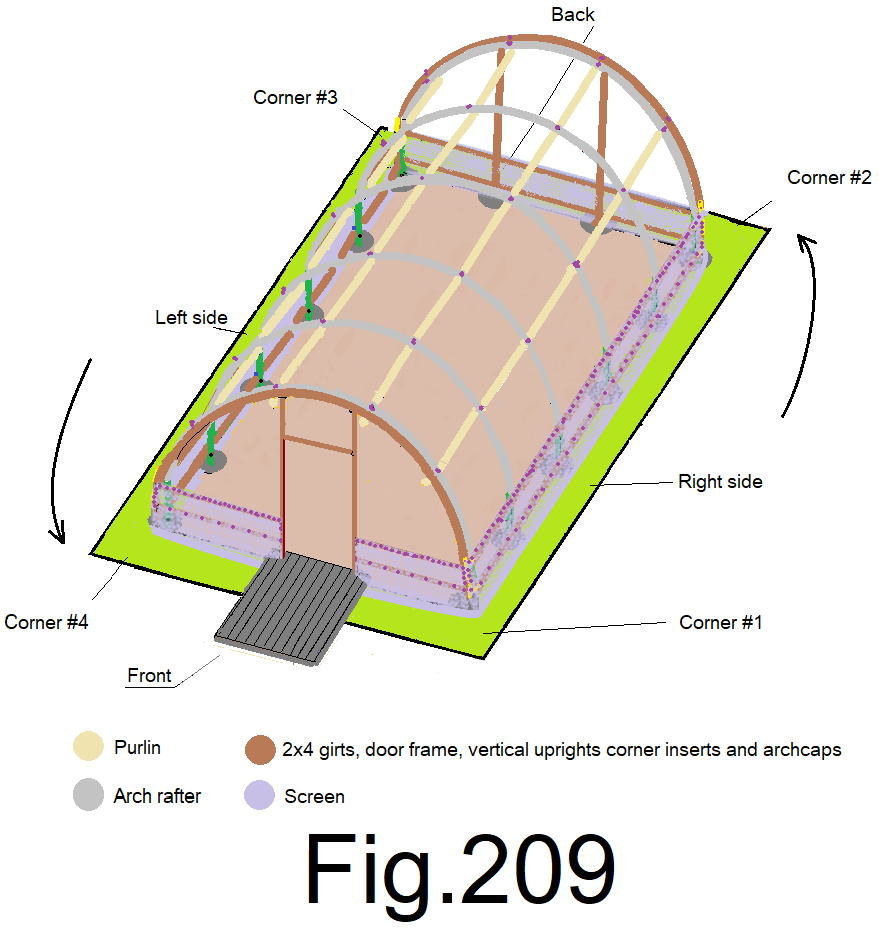
The bottom end wall screen and side wall screen is done, except where the screen meets the ground. Leave it for now, we will get back to that later. Let’s move on…
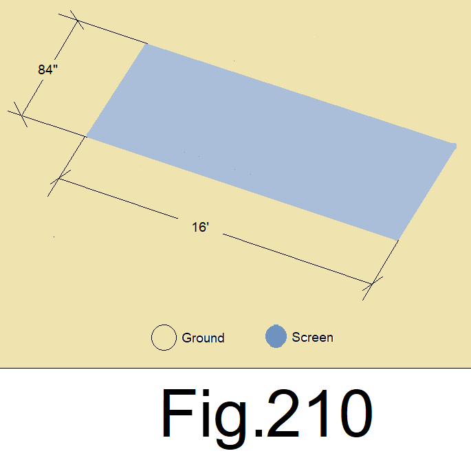
214) Lay out 84 in. wide bug screen flat on the ground, measure and cross cut it at 16 ft. Use a pair of large fabric scissors, a razor knife or (use a small electric soldering iron if the screen is woven, nylon based and subject to unraveling). Carefully cut the bug screen. Fig. 210
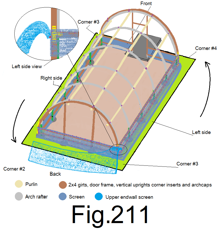
215) At the back left corner, hold the bottom of one corner of the 16 ft. long by 84 in. wide bug screen, leaving 6 inches extra beyond the grab point along the side. Position yourself under the screen and hold the screen to the back end wall upper girt at the left corner, over top of the lower screen and with bottom edge of the upper screen flush to the bottom edge of the upper girt. Attach it with a staple. Fig 211
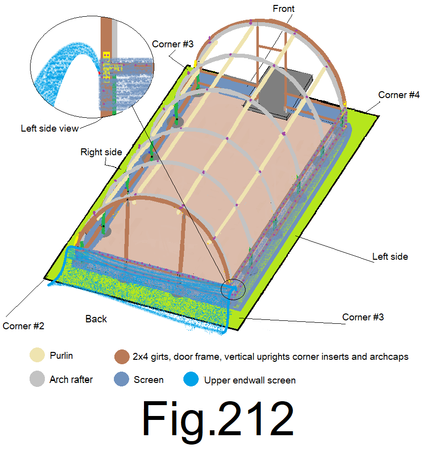
216) At the back right corner, position yourself under the screen, hold the bottom of the screen to the top girt at the back right corner, bottom edge flush to the bottom edge of the upper girt, not to tight, leave enough slack so that the screen sags about 1ft. at the center and fasten with a staple. Fig 212
217) At the center of the back wall, from under the screen, pull the screen straight up and staple the bottom of the screen to the bottom edge of the upper girt while holding the screen centered end to end and bottom edge flush to the bottom edge of the upper girt. Fig 213
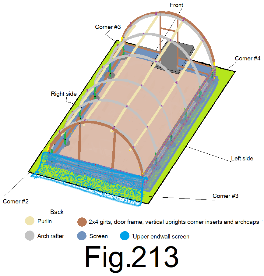
218) At the quarters of the back wall, from under the screen, pull the screen straight up and staple the bottom of the screen to the upper girt while holding the screen bottom edge flush to the bottom edge of the upper girt.(2 locations). Fig 214
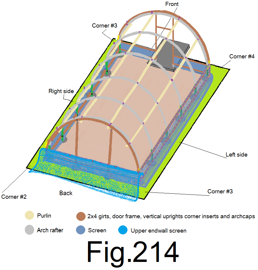
219) At the eighths of the back wall, from under the screen, pull the screen straight up and staple the bottom of the screen to the upper girt while holding the screen bottom edge flush to the bottom edge of the upper girt. (4 locations) Fig 215
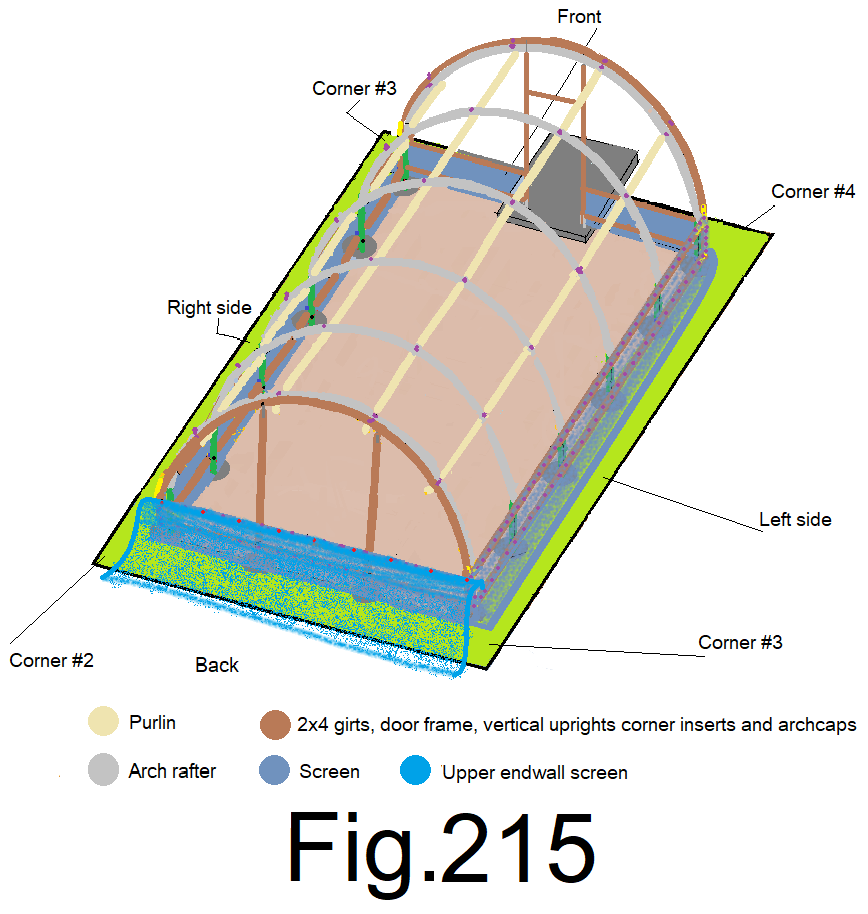
220) At the sixteenths of the back wall, from under the screen, pull the screen straight up and staple the bottom of the screen to the upper girt while holding the screen bottom edge flush to the bottom edge of the upper girt. (8 locations) Fig 216
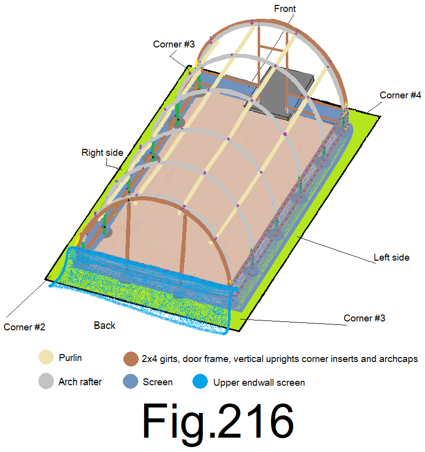
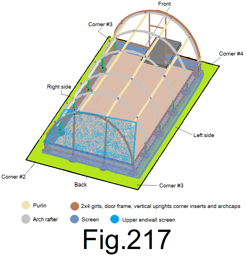
221) Using a 6 ft or 8 ft step ladder, at the center of the back wall, slightly tension the screen straight up over the top of the end wall cap and staple it to the top of the end wall cap. Fig 217
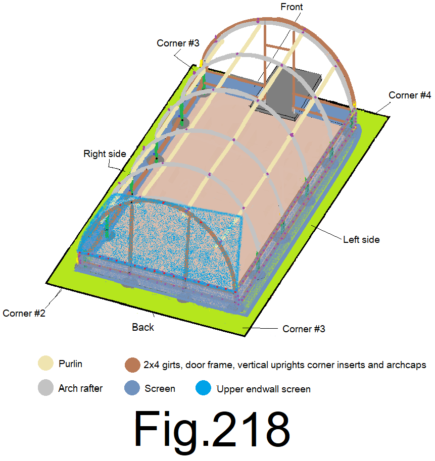
222) At the quarters of the back end wall, slightly tension the screen straight up and staple it to the top of the end wall cap. (2 locations) Fig 218
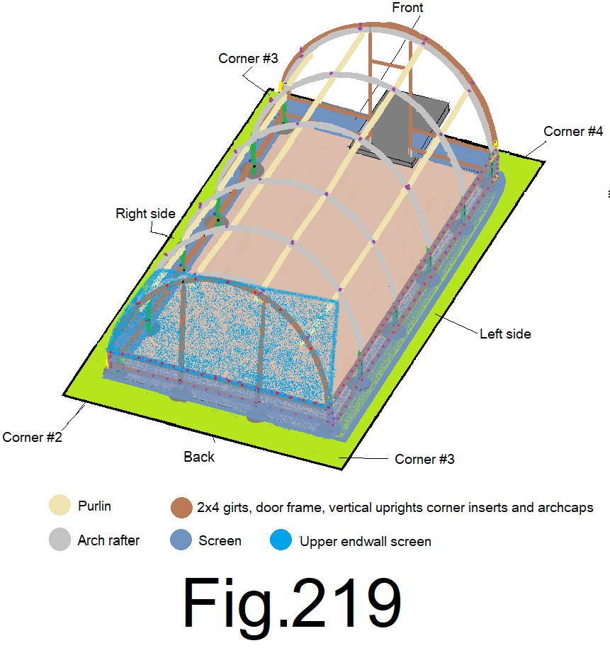
223) At the eighths of the back end wall, slightly tension the screen straight up and staple it to the top of the end wall cap. (4 locations) Fig 219
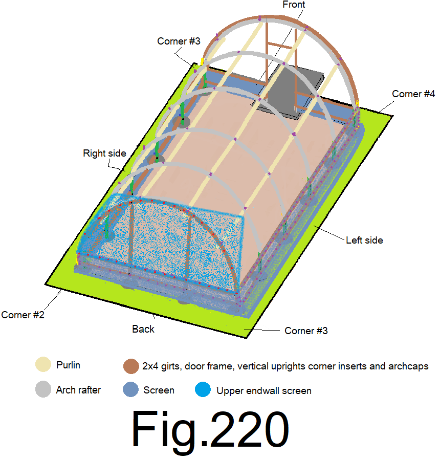
224) At the sixteenths of the back end wall, slightly tension the screen straight up and staple it to the top of the end wall cap. (8 locations) Fig 220
225) Staple the screen to the top of the end wall cap every 4 inches. Fig 221
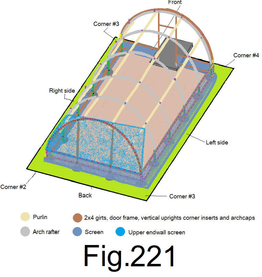
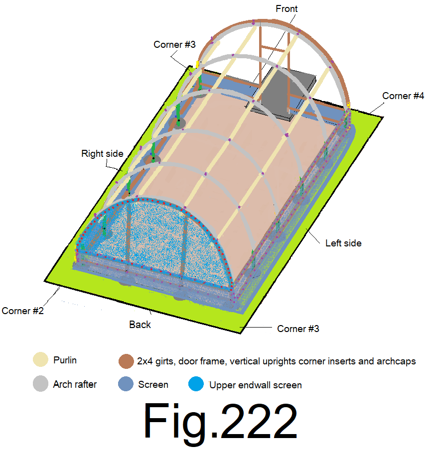
226) Trim the screen along the top of the back end wall leaving about 4in. extra. Use a pair of large fabric scissors, a razor knife or (use a small electric soldering iron if the screen is woven, nylon based and subject to unraveling). Carefully cut the bug screen. Fig 222
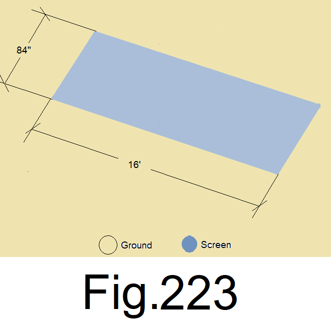
227) Measure out 16 ft. of 84 in. wide bug screen flat on the ground and cross cut it. Use a pair of large fabric scissors, a razor knife or (use a small electric soldering iron if the screen is woven, nylon based and subject to unraveling). Carefully cut the bug screen. Fig. 223
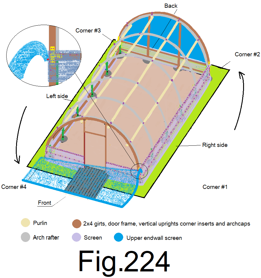
228) Grab the bottom of one corner of the 16 ft. long by 84 in. wide screen, at 6 in. in from the outside edge of the screen. Position yourself under the screen. Hold the screen to the front end wall top girt at the right corner. Position the upper screen over top of the lower screen with the bottom edge of the upper screen flush to the bottom edge of the end wall top girt and attach it with a staple. Fig 224
229) At the front left corner, from under the screen, hold the bottom of the screen to the upper girt, over top of the lower screen and with the bottom edge of the screen flush to the bottom edge of the top girt. Leave enough slack so that the screen sags about 1ft. at the center and attach with a staple. Fig225
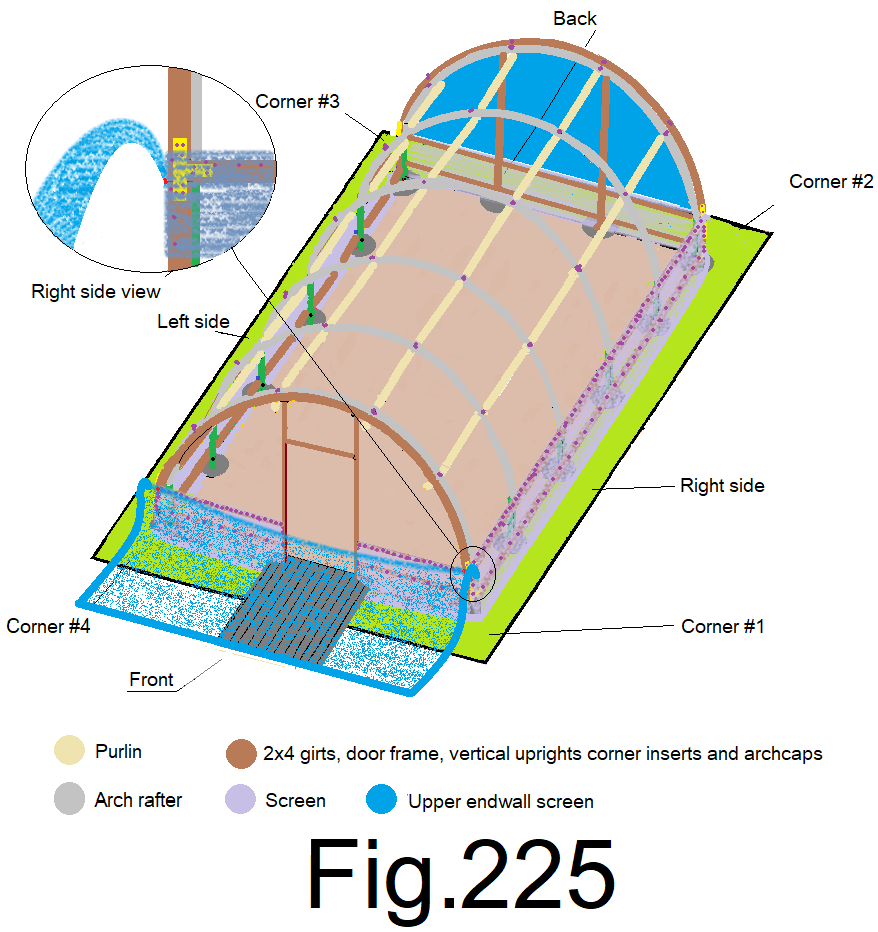
230) At the off center of the front wall at the right side of the door frame, from under the screen, pull the bottom of the screen straight up and staple it to the top girt while holding the bottom edge of the screen flush to the bottom edge of the top girt. Repeat at the left side of the door frame. Fig 226
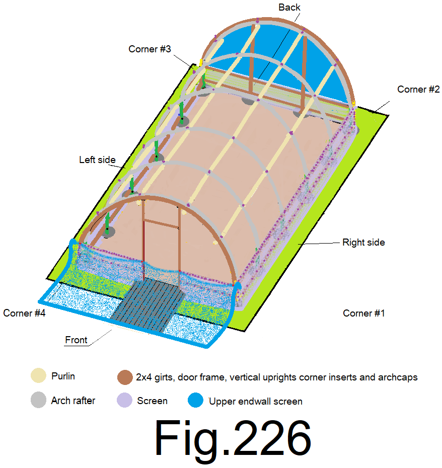
231) At the quarters of the front wall, from under the screen, pull the bottom of the screen straight up and staple it to the top girt while holding the bottom edge of the screen flush to the bottom edge of the top girt. (2 locations) Fig 227
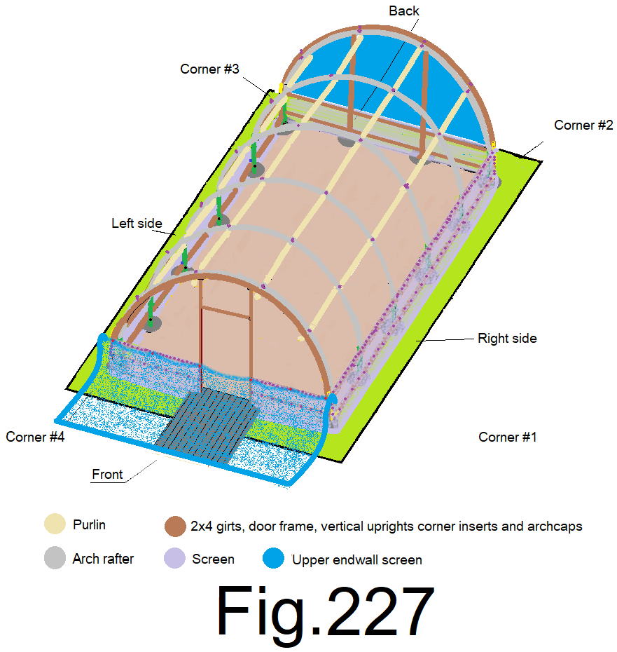
232) At the eighths of the front wall, from under the screen, pull the bottom of the screen straight up and staple it to the top girt while holding the bottom edge of the screen flush to the bottom edge of the top girt. (4 locations) Fig 228
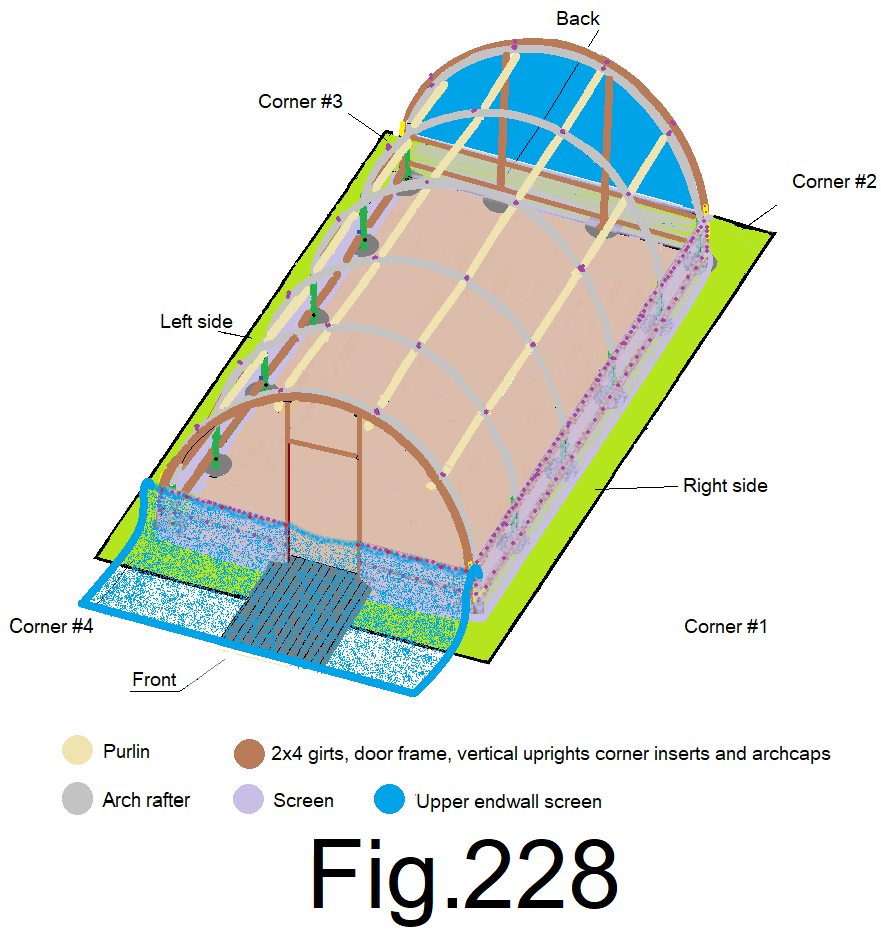
233) at the sixteenths of the front wall, from under the screen, pull the bottom of the screen straight up and staple it to the top girt while holding the bottom edge of the screen flush to the bottom edge of the top girt (8 locations) Fig 229
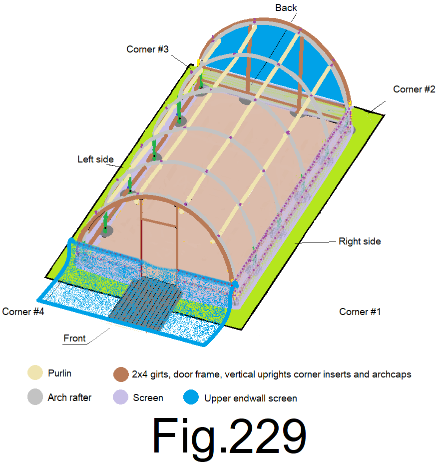
234) Using a 6 ft or 8 ft step ladder, get under the screen at the center of the front wall, pull the right top of the screen straight up along the right side of the door frame and staple it to the top of the front end wall cap, while allowing the extra screen to rest loosely on top of the roof frame. Repeat at the left side of the door frame. Look closely at the lines in the screen and use them to assist in lining up the screen to the door frame before fastening the screen to the top of the end wall cap. Fig 230
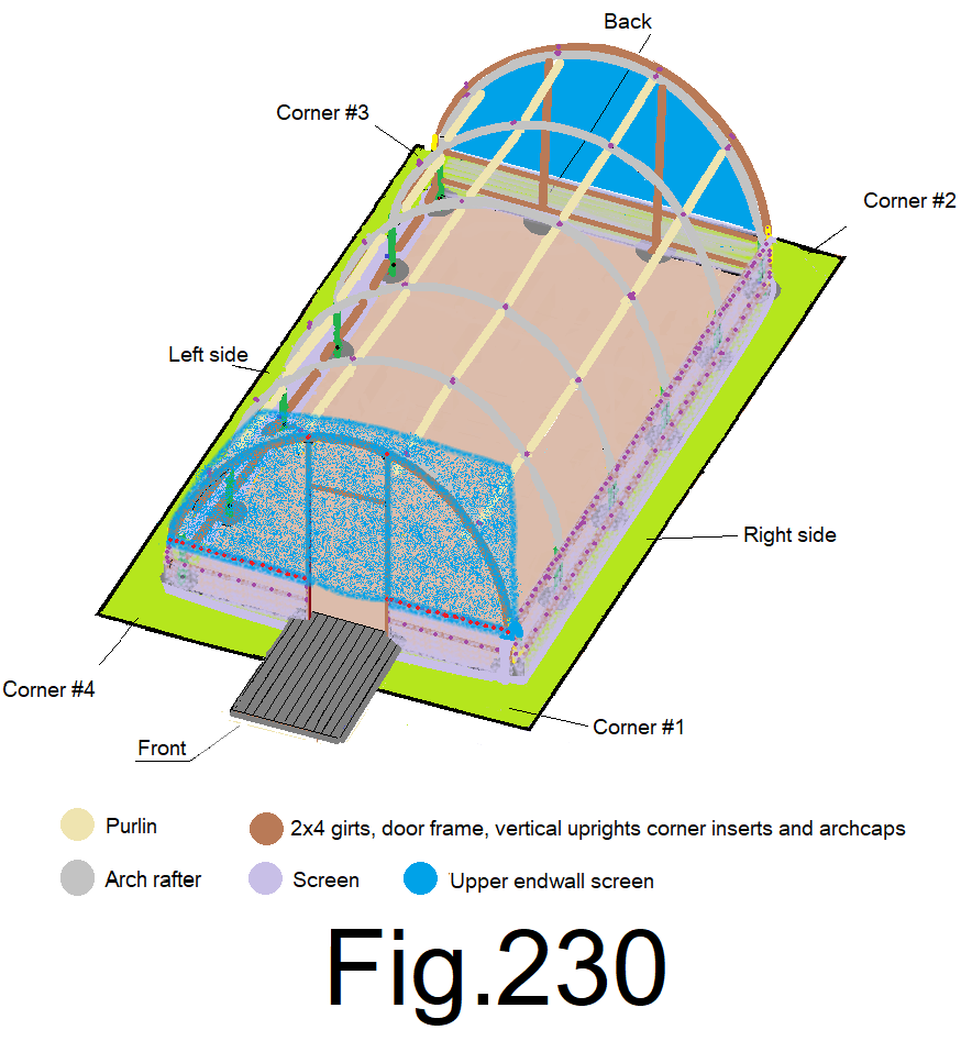
235) At the quarters of the front wall, slightly tension the screen straight up and staple it to the top of the end wall cap, (2 locations). Fig 231
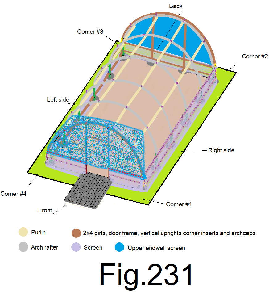
236) At the eighths of the front wall, slightly tension the screen straight up and staple it to the top of the end wall cap. (4 locations) And staple at the top center. Fig 232
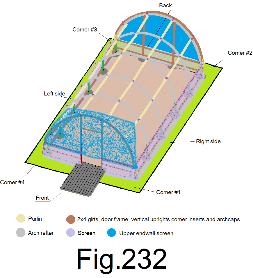
237) At the sixteenths of the front wall, slightly tension the screen straight up and staple it to the top of the end wall cap, (8 locations). Fig 233
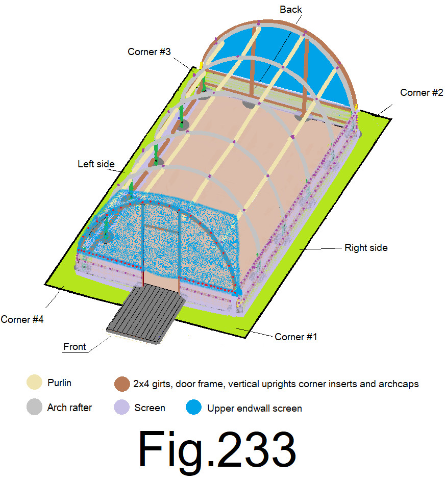
238) Staple the screen to the top of the end wall cap and along the outside of the door frame at every 4 inches. Fig 234
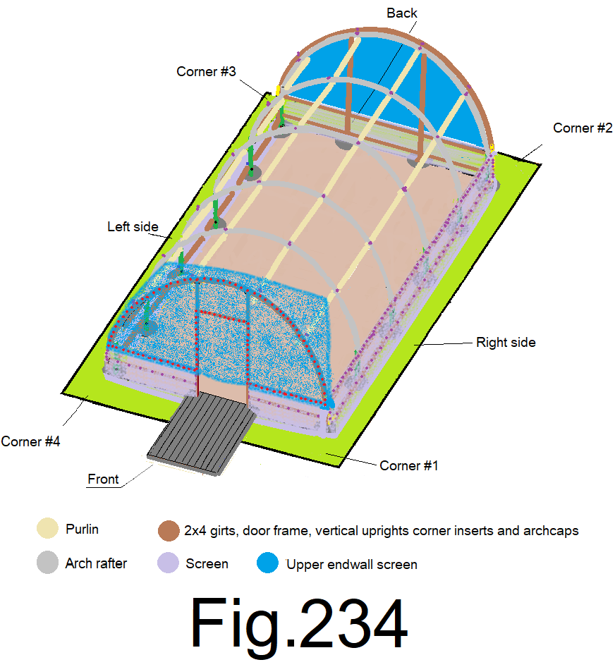
239) Trim the screen along the top of the end wall leaving 4in. minimum extra. Trim the screen at the door frame, tight to the frame. Use a pair of large fabric scissors, a razor knife or (use a small electric soldering iron if the screen is woven, nylon based and subject to unraveling). Carefully cut the bug screen. Fig 235
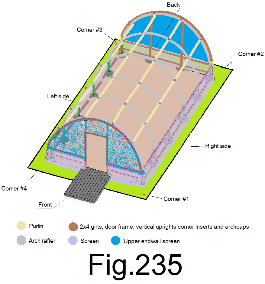
Wall screen done and now it’s time for the poly film roof covering.
The wind must be calm when the poly film is set and fastened because the poly film has an extreme “sail” quality and it is very difficult to handle in any wind at all.
240) Unroll or unfold and place, top side up, a 22 ft. wide by 22 ft. long piece poly film roof covering on the ground along the right side wall. Do not step on it or snag it on anything. Fig 236
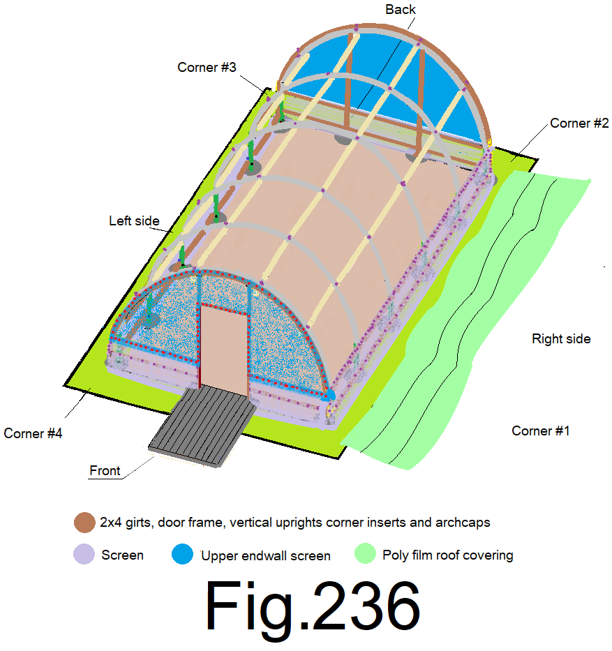
241) Bunch up the poly film about 16 in. along the edge, in the middle and at the ends, one at a time as you tie 3) 30 ft. ropes to the poly film, (3 raps each) and with a simple square knot oriented to the underside of the poly film, one in the middle and one at each end. Throw the other end of the ropes over the roof to the left side. Fig 237
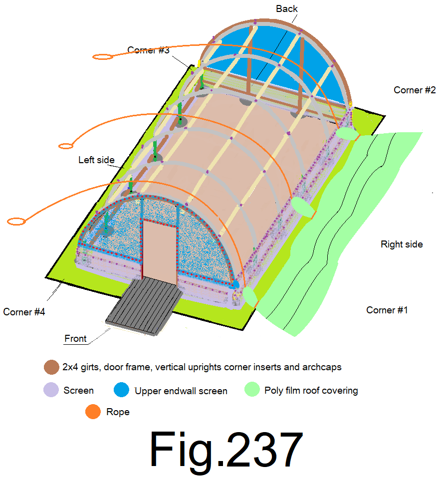
242) Set 3) stakes into the ground evenly spaced along the left side, out away from the side wall as much as possible or out about 4 ft. Fig 238
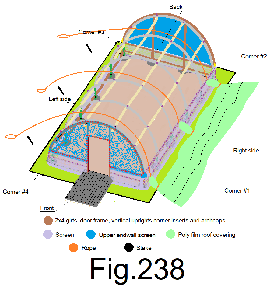
243) Pull each rope one at a time until the leading edge of the poly film is raised about 4ft off the ground, and temporarily tie each rope to the corresponding stake as you proceed. Fig 239
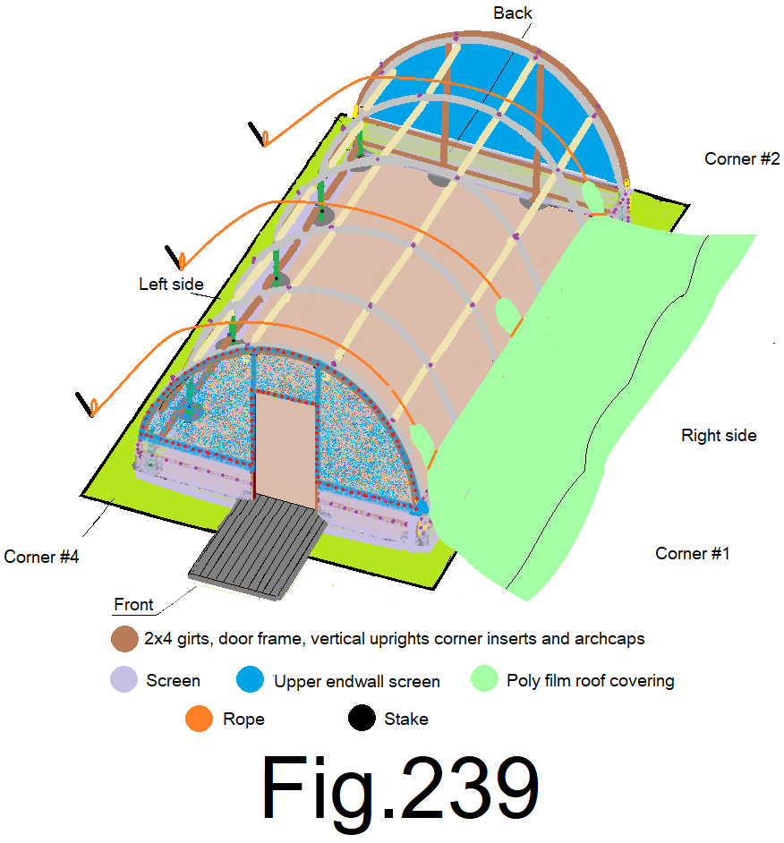
244) Un-tie the first rope from the stake and pull more (about 2 ft. increments), and then re-tie it, repeat at the other 2 ropes. On the other side, help the poly film unfold if need be. Fig 240
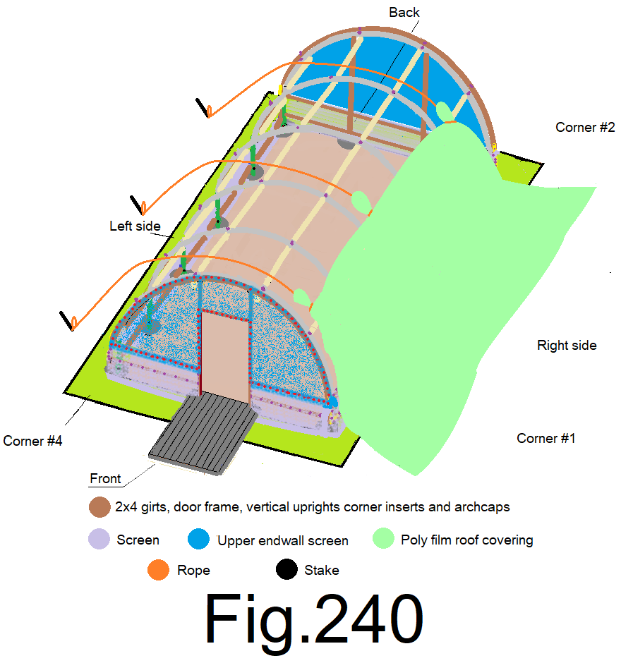
245) From the inside, underneath, and with a step ladder, help the poly film, gently by hand as it is pulled over the top, pull each rope a little, tie it to the stake, then from the inside help the poly film over the roof frame, over and over and don’t let the poly film snag or get jammed up on the roof frame. Fig 241
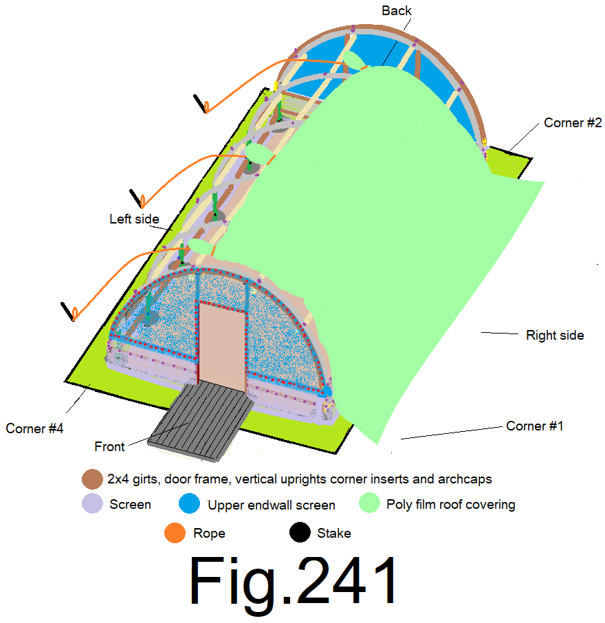
246) Repeat step 244) and 245) until the poly film can be reached by hand from the left side, and pull the poly film roof covering over until it is relatively evenly up on top. Fig 242
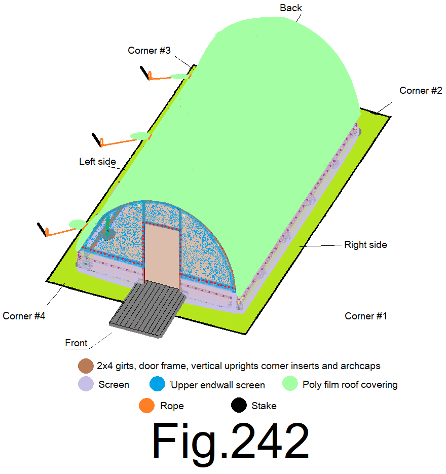
247) Un tie the ropes from the poly film and the stakes and remove the stakes. Adjust the poly film at the top centers at each end and at all four corners and along the side walls, until the poly film roof covering is evenly laying on the roof frame. There should be an even amount of extra poly film beyond the ends and sides all the way around. Fig 243
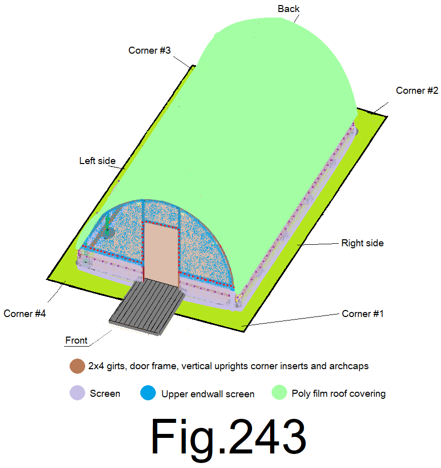
248) At the front end wall, mark a 6 in. line at the front top center of the poly film where it folds over the top outside edge of the end wall cap. Attach a 6 in. peace of duct tape to the poly film just below the marked line. Fig 244
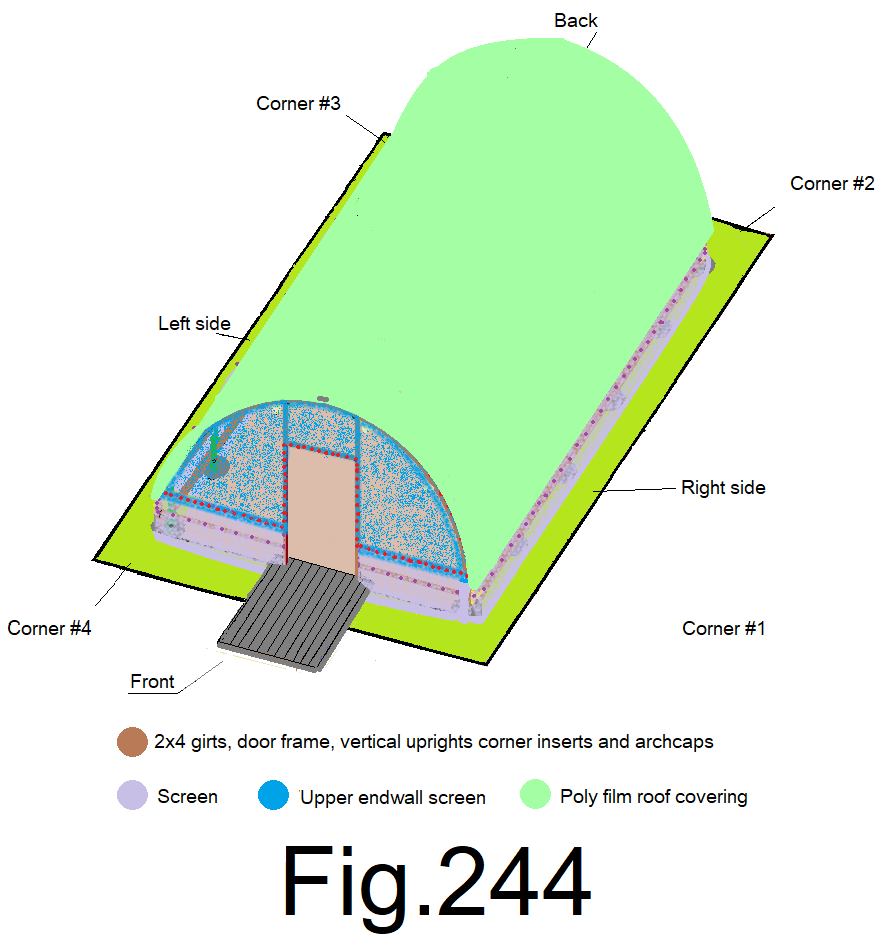
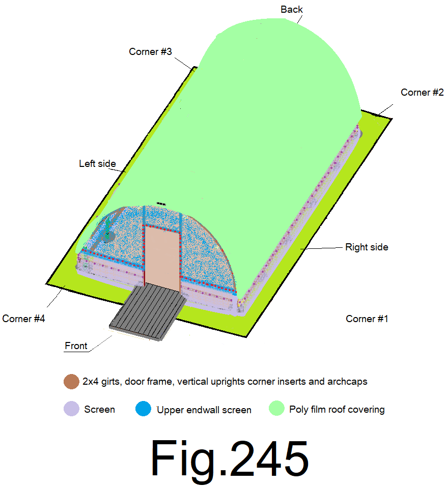
249) Pull ever so slightly down at the center of the poly film and staple at the center of the duct tape to the outside edge of the end wall cap. Pull slightly down 3 in. to the right and staple the right side of the duct tape to the leading edge of the end wall cap. Pull slightly down 3 in. to the left and staple the left side of the duct tape to the leading edge of the end wall cap. Fig 245
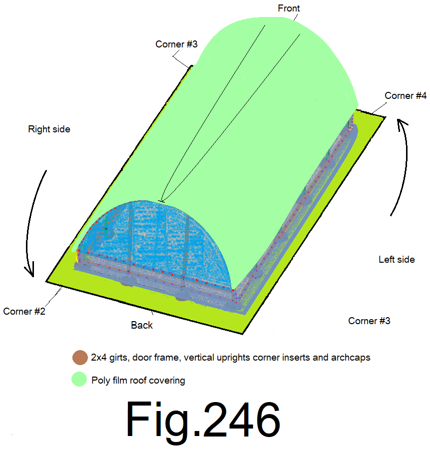
250) At the back end wall top center, pull the poly film with one hand, straight back and then down over the arch cap, keep tension on it, with the other hand make a 6 in. mark where the center of the poly film bends over the outside corner edge of the end wall cap. Fig 246
© 2021