Greenhouse construction tutorial. How to JDPShack. Directions part 3.
John Pandrea
ALWAYS WEAR SAFETY GLASSES, EAR PROTECTION, WORK GLOVES WHEN HANDLING METEL AND A DUST MASK WHEN DIGGING HOLES, MIXING CEMENT and CUTTING or DRILLING.
How to JDPShack
Construction directions continued…
Steps 101-150
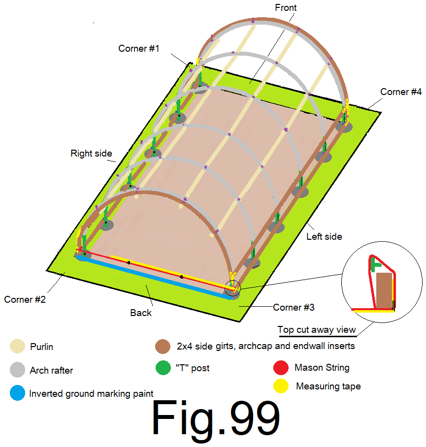
101) Measuring from the outside edge of the left side 2×4 side wall corner insert, next to the string, mark the string at 4 ft. 8 in. and again at 9 ft. 4 in. Fig 99
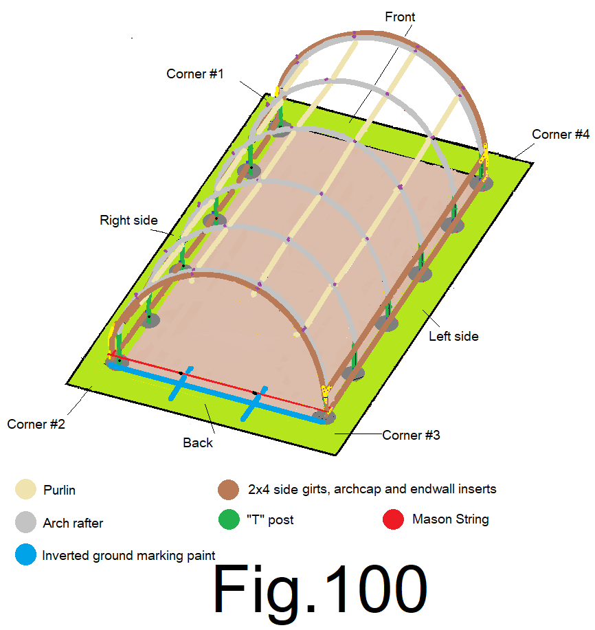
102) using a spray can of “inverted marking paint”, mark a cross line directly under the 4 ft. 8 in. mark on the string and the 9 ft. 4 in. mark on the string. Fig 100
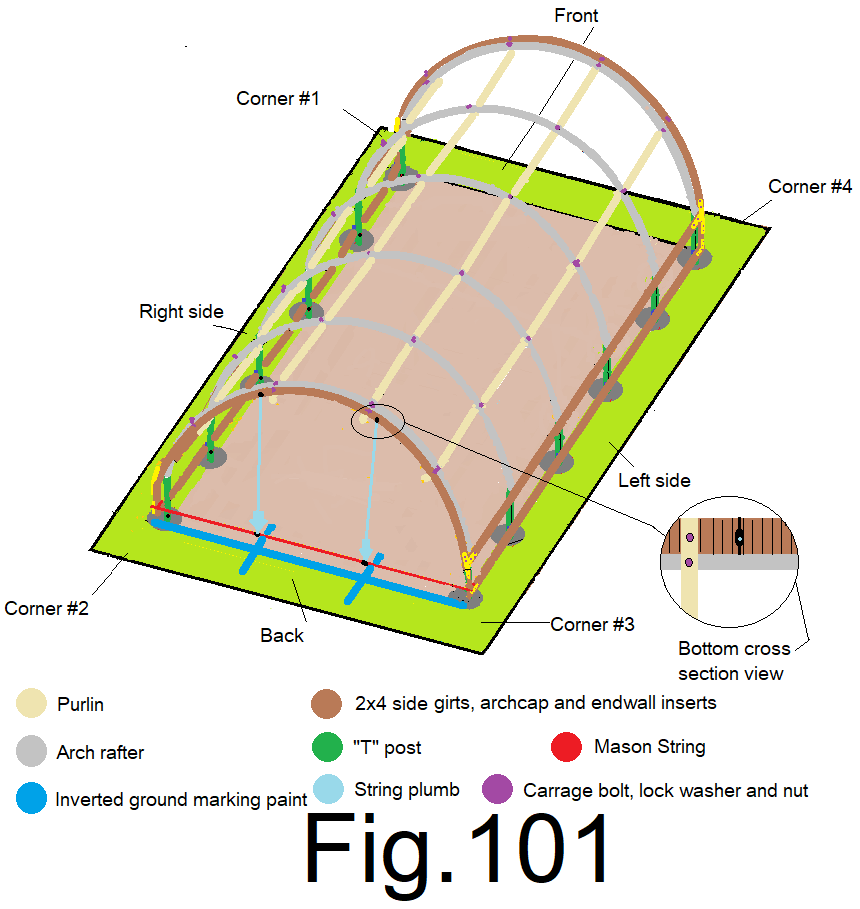
103) Using a step ladder and a string plumb, plumb up from one of the marks on the string to the bottom of the end wall cap and mark it. Using a speed square, cross mark the bottom of the end wall cap at the mark, and transfer the mark to the outside edge of the end wall cap. Repeat at the other mark on the string. Fig 101
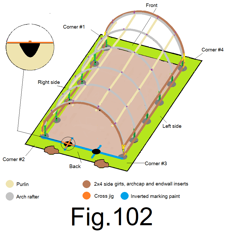
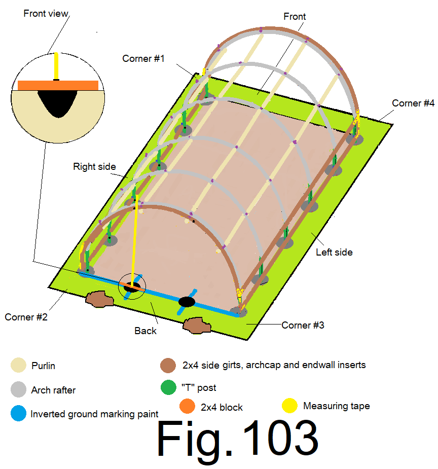
104) Remove the mason string and dig a 12 in. deep by 12 in. wide hole at each painted cross, using the cross jig from step 17). Fig 102
105) Place a 2×4 by 24 in. long block across the right side freshly dug hole and measure from the top of that block straight up to the bottom of the end wall cap at the mark from step 103). Cut a 2×4 at that length and mark it “R”. Repeat at the left side hole and mark it “L”. Fig 103
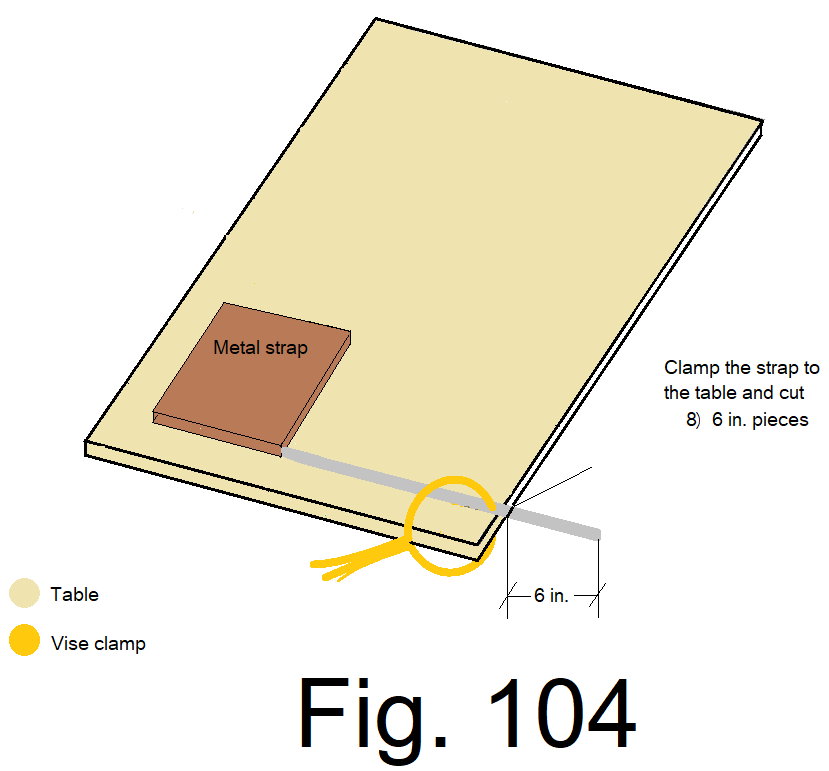
106) From step 78), Using the table, clamp, “saws all”, and “Simpson Strong Tie” 1 inch metal strapping, cut eight 6 in. metal straps. Fig 104
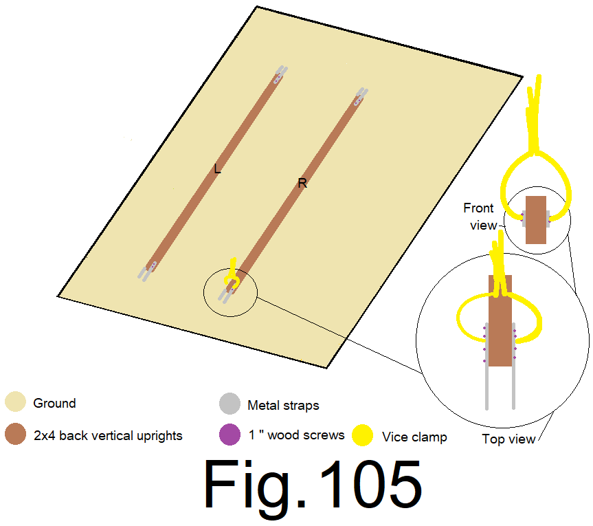
107) Using vise grip “C” clamps and 1 inch wood screws. Attach the eight 6 in. straps to both sides of both 2x4s at both ends, centered and even, leaving half of the strap extended beyond the 2×4. Fig 105
108) Bend the metal strap 90o out at ½ in. on the right side and ¾ in. on the left side beyond the top of the left side vertical 2×4. Hold the center of the 2×4 to its corresponding mark on the bottom of the end wall cap. Line up the back outside edges of the end wall cap and vertical 2×4 flush. Leave a 1/2 in. gap between the top of the vertical 2×4 and the bottom of the end wall cap and clamp the vertical 2×4’s metal straps to the bottom of the end wall cap on both sides of the vertical 2×4. Secure the straps to the end wall cap using 1 inch wood screws from the bottom. Repeat for the right side vertical 2×4. Fig 106
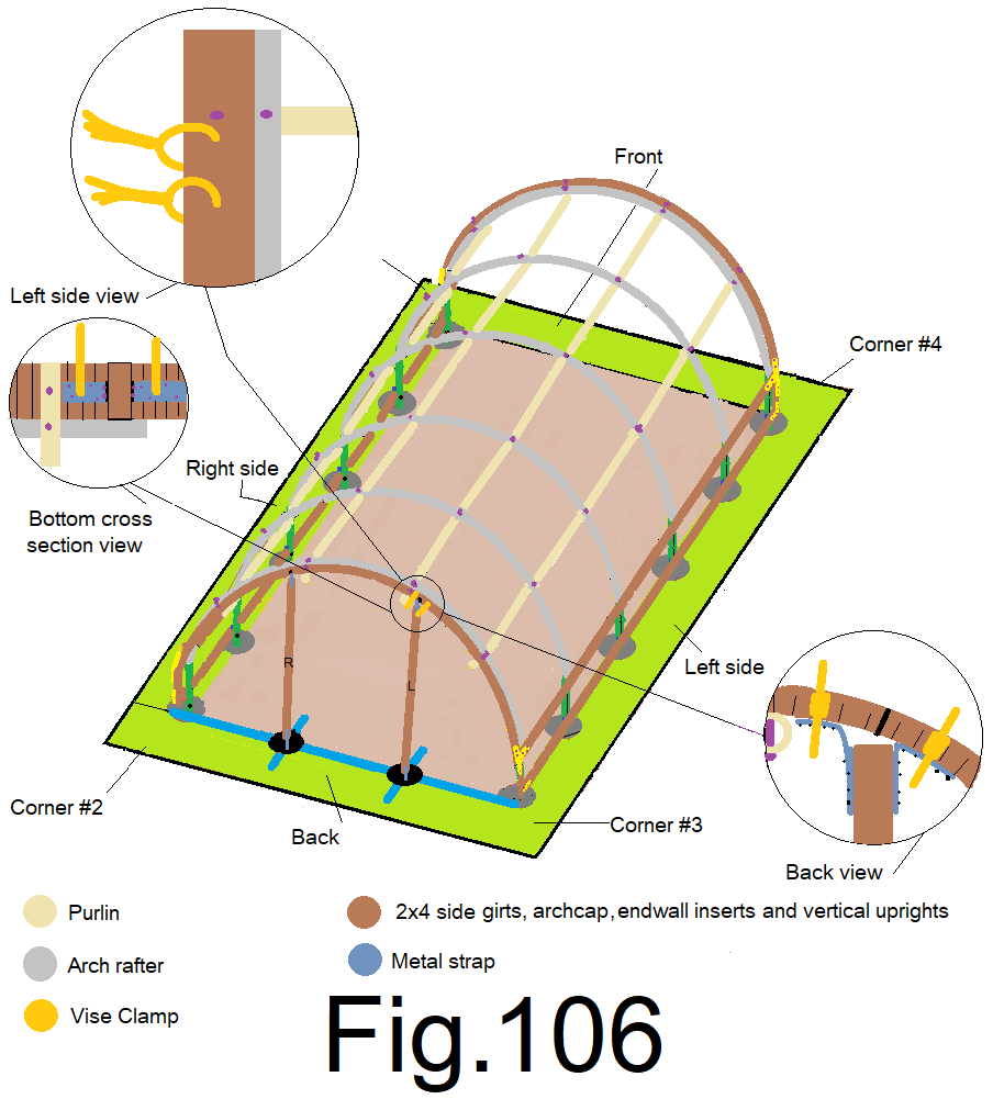
NOTE; both 2x4s should hang straight down to about 1 in. above their corresponding hole with the 2) straps on the bottom of each 2×4 extending into the hole.
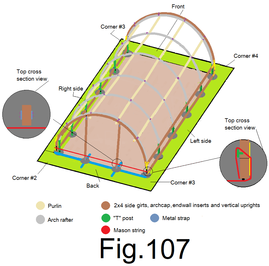
109) Reattach and tension the mason string between the back corner inserts near the bottom side girt, and add a carpenters pencil as a spacer between the string and the 2×4 corner inserts on both sides. Mix up enough concrete to fill the 2 holes with 1 cubic ft. each. Approximately 2 cubic ft. total. There should be a ½ to 1 in. gap between the top of the cement filled hole and the bottom of the vertical 2×4, the bottom of the straps should be submerged into the cement. Use a level to plumb the vertical 2x4s from side to side and use the mason string as a reference to plumb the vertical 2x4s front to back. Remember to leave a carpentry pencil sized gap between the string and the vertical 2x4s. The metal strapping should hold the vertical 2x4s as they are imbedded into the cement. Check plumb and re-set the vertical 2x4s if necessary as the cement sets up. Use a hand float to finish the cement and slop the cement slightly from the center, outward, so that it will shed water after it sets up. Fig. 107
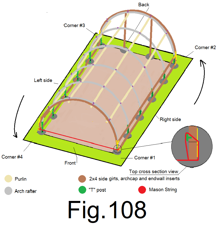
110) At the right front corner attach a mason string to the 2×4 front right sidewall corner insert, down near the bottom girt. Extend the string along the front end wall and attach it to the left side 2×4 sidewall insert, down near the bottom girt. Orient the string to the outside edge of the 2×4 corner inserts and tighten the string. Fig 108
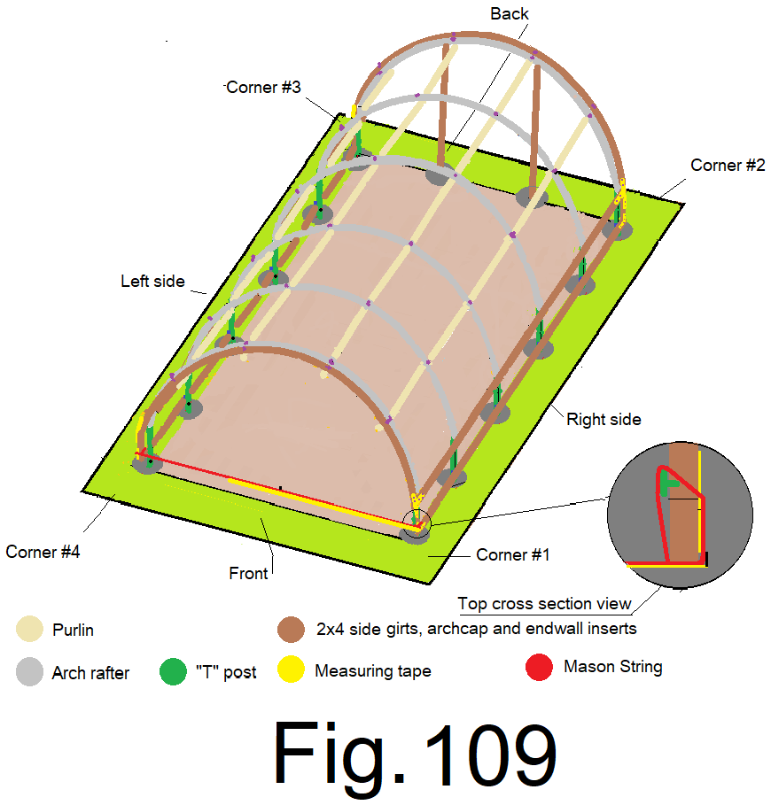
111) Measure from the outside edge of the 2×4 right side wall corner insert, along the string, mark the string at 7 ft. Fig 109
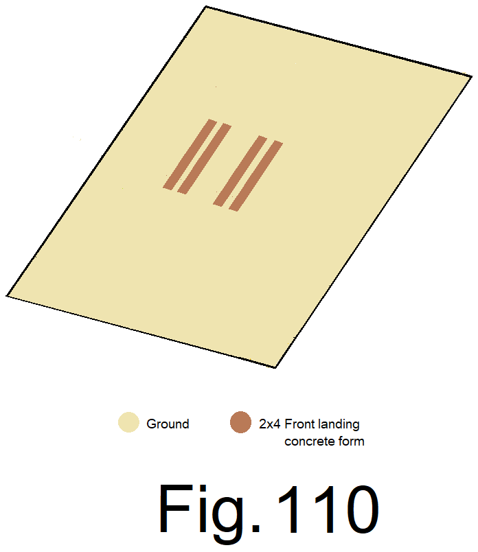
112) cut 4) 2x4s at 4 ft. Fig 110
113) Using 8) 3 in. wood screws attach the 2x4s together making a rectangle shape. Fig 111
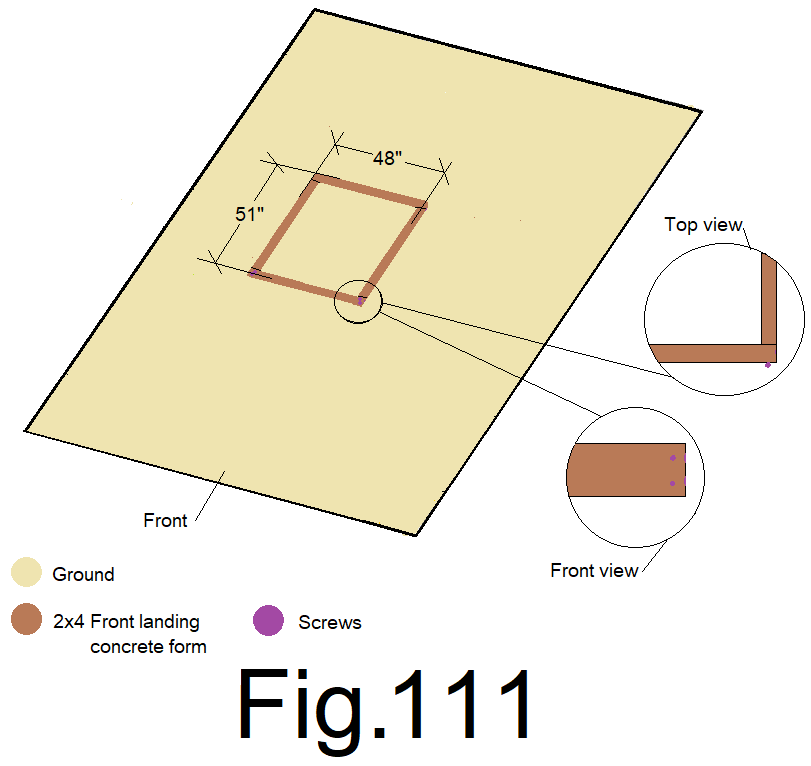
This rectangle shape is the concrete form for the front landing at the front entrance. The sides are 51 inches long and the ends are 48 inches long.
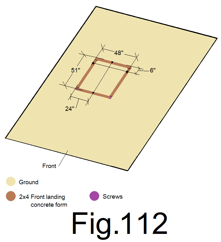
114) Measure from the back of the form at both corners, along both sides, and make 2 marks at 6 in. And measure from the left side at both corners, along both ends, and make 2 marks at 24 inches. Fig 112
115) Place the rectangle on the ground at the center of the front end wall with the 6 in. marks directly under the string and the 2ft. marks centered to the 7 ft. mark on the string. Set two 24 in. form stakes evenly spaced along the back of the form. Fig 113
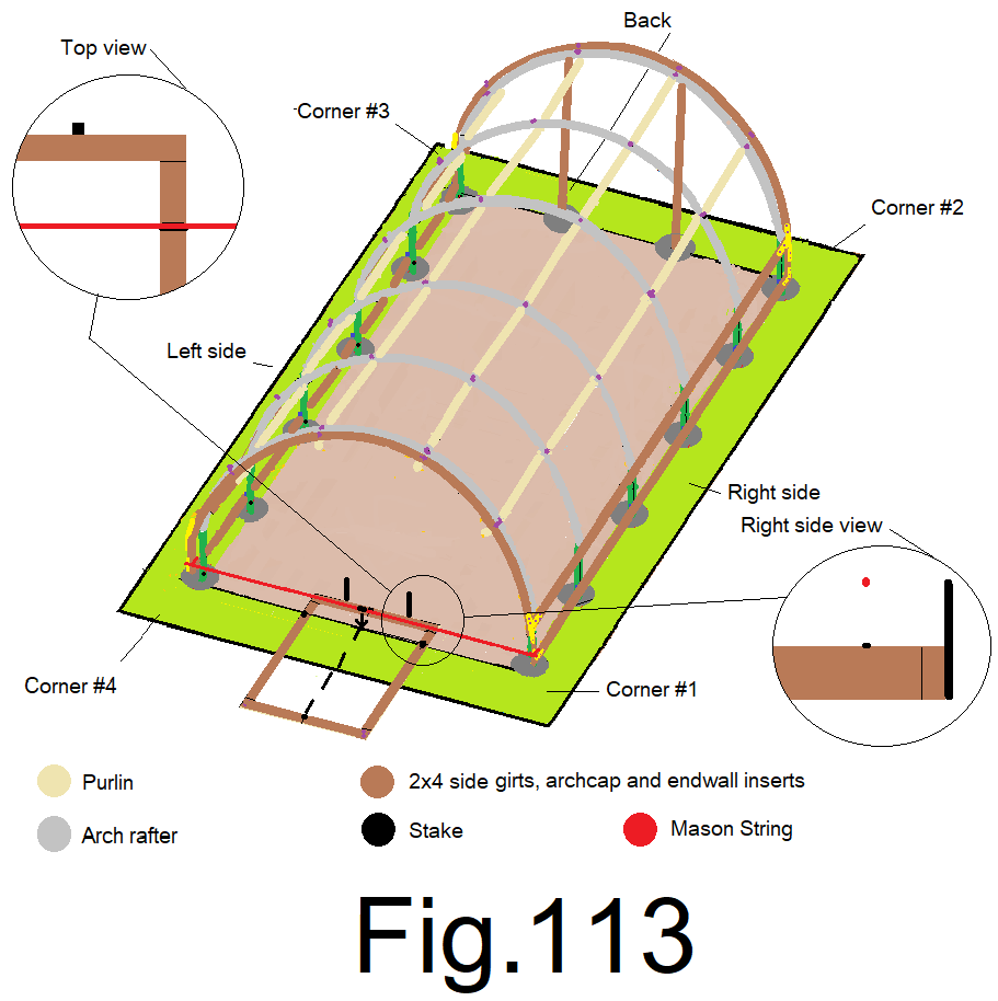
The front landing must slope slightly to the front or outside.
116) Raise the back or inside of the form 1 in., or higher if necessary to achieve a slope to the front and attach the form to the right side stake using a roofing or wood screw. Fig 114

117) place a small level across the back form board. Level the form board and attach it to the other stake. Fig 115
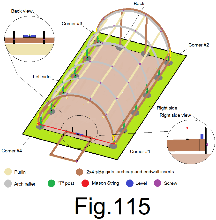
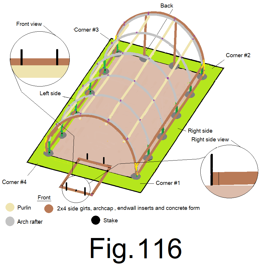
118) Remove the mason string and set 2) stakes evenly spaced along the front end of the form board. Fig 116
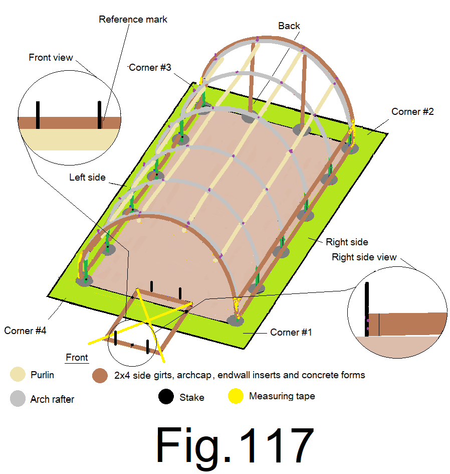
119) Measure from one of the outside corners on the back of the form, diagonally to the opposite outside corner on the front of the form. Adjust the front of the form from side to side until the reading at the front corner reads 707/16 in., a calculated number, remember that formula (a2+b2=c2), this time…. where a=48 and b=51 and then c=707/16. Then check it, pull tape along both diagonals and adjust the front end from side to side until the 2) diagonal numbers are the same, and then mark a line on the outside of the form along one of the stakes in order to mark reference “square”. Fig 117
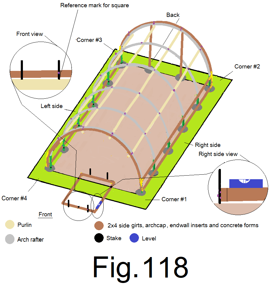
120) Place a small level on the right side form and adjust the right front corner up or down until the side form slopes at least one full bubble from the back to the front, then attach the right front stake to the front form board keeping the marked reference line from step 131) tight to the outside edge of the stake in order to hold “square”. Fig 118
121) Place a small level on the front form board and adjust the left corner of the front form board up or down until it reads level and then secure the front form board to the left front stake. Set 2 more stakes, 1 on each side of the side forms, centered, attach the stake to the side form with screws. Fig 119
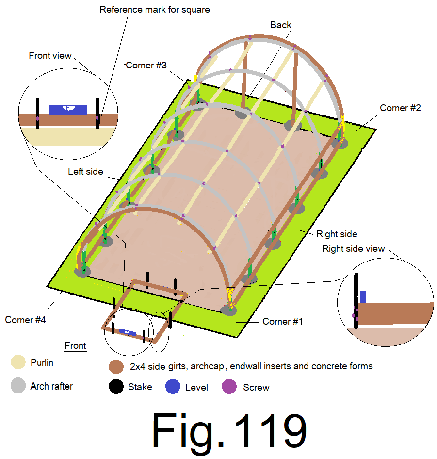
Your front landing concrete form should be centered side to side, square, level side to side, and should slope slightly toward the front. Double check it with a measuring tape and small level. If any of your readings are a little off, that’s OK. However, the form shall slope toward the front.
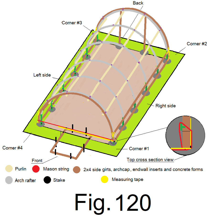
122) Re-attach a mason string, like in step 110) and tighten it. Measure from the outside edge of the 2×4 side wall corner insert, along the string; mark the string at 5 ft. 6 in and 8ft. 6in. Fig 120
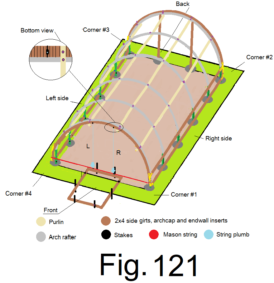
123) Using a string plumb, plumb straight up from the 5 ft. 6in. mark on the string and mark the bottom of the end wall cap. Plumb up from the 8 ft. 6 in. mark on the string and make a mark on the bottom of the end wall cap. The marks on the bottom of the end wall cap should be precisely 36 inches apart, check this reading on the bottom of the end wall cap. Use a speed square and make cross marks over the marks on the bottom of the end wall cap and transfer the marks to the outside or front edge of the end wall cap. Fig 121
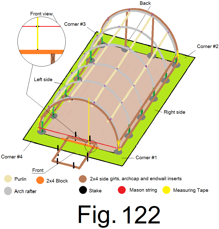
124) Place a 5 ft. long 2×4 block across the front landing concrete form, directly under the string. Measure from the top of the block, directly under the 5 ft. 6 in. mark on the string, (right side), up to the bottom of the end wall cap at the corresponding mark. Cut a 2×4 at that length, mark the 2×4 with an “R”, for right side. Fig. 122
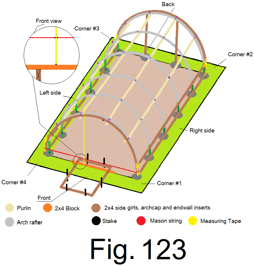
125) Measure from the top of that block, directly under the 8 ft. 6 in. mark on the string, (Left side), up to the bottom of the end wall cap at the corresponding mark. Cut a 2×4 at that length (mark the 2×4 with an “L”, for left side. Fig. 123
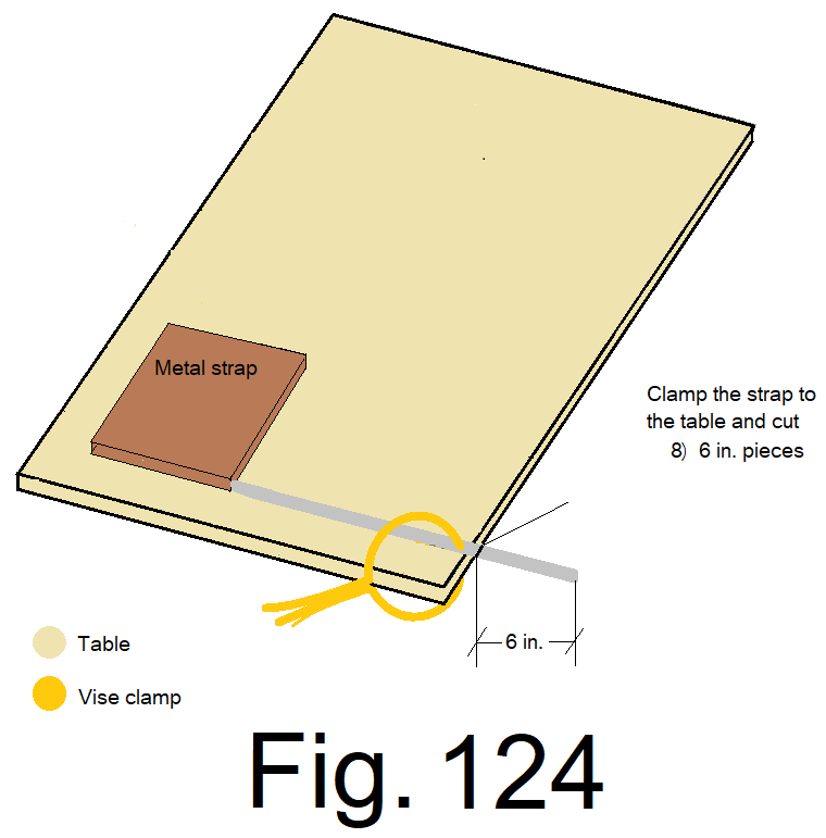
126) Like step 106) , using the “Simpson Strong Tie” 1 inch strapping, cut eight 6 in. straps. Fig104. Fig 124
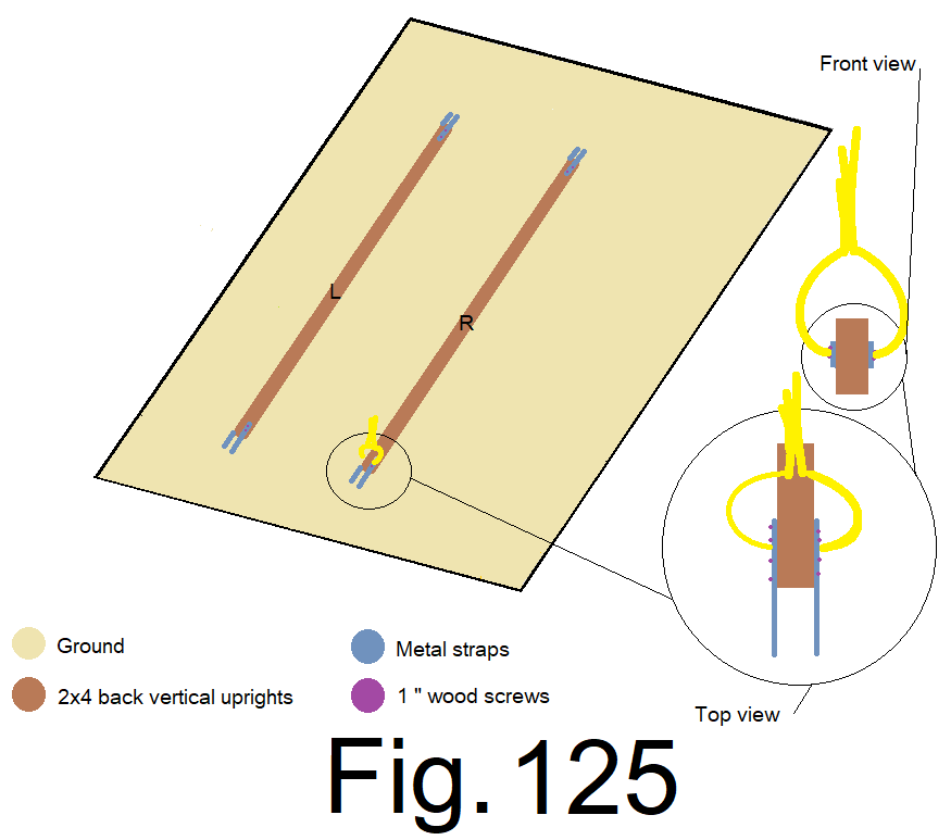
127) Repeat step 107) , Using vise grip “C” clamps and 1 inch wood screws. Attach 2) 6 in. metal straps to the sides of both 2x4s at both ends, centered and even, leaving half of the strap extended beyond the end of the 2×4. Fig 105. Fig 125
128) Measure and cut a 5 ft. “1×4” and use it to replace the 2×4 across the front landing concrete form under the string. Place the right side vertical 2×4 on top of the 1×4 block. Line up the left edge of the vertical 2×4 to its corresponding cross mark on the bottom of the end wall cap. Line up the front edge of the end wall cap and the front edge of the vertical 2×4. There should be an approximate ¾ in. gap between the top of the vertical 2×4 and the bottom of the end wall cap at the mark, bend the straps to fit and clamp the straps to the bottom of the end wall cap on both sides of the 2×4. Secure the straps to the bottom of the end wall cap using 1 inch wood screws. Repeat this step for the left side vertical 2×4. Fig 126
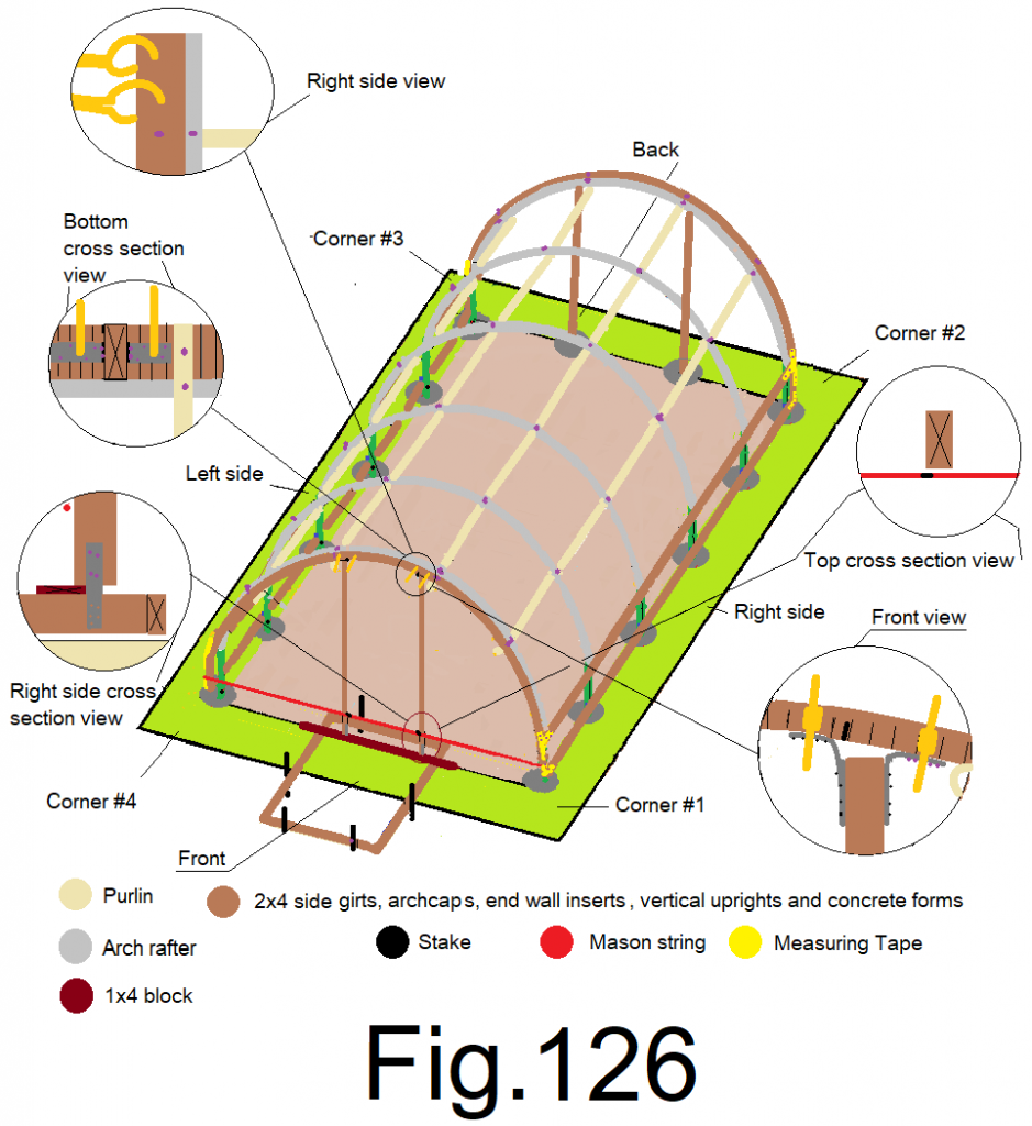
NOTE; Both vertical 2x4s should be oriented straight down as they rest on the edge of the 1×4 block, which is across the front landing concrete form.
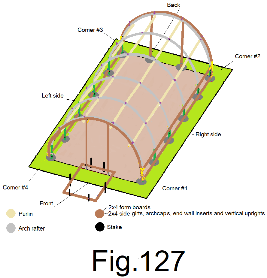
129) Remove the mason string and remove the 1×4 block. It is OK if the vertical 2x4s move out of position as they are hanging straight down from the arch cap. Fig 127
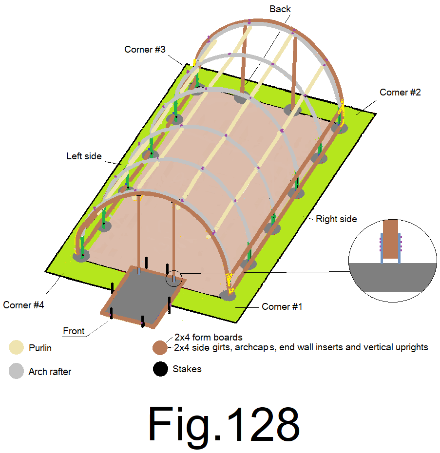
130) Mix up about 8 cu ft. of cement using the formula from step 57) with a cement mixer or by hand in a wheel barrow with a garden hoe or spade shovel. Use 3 parts “#4 gravel”, 2 parts “#3 sand” and 1 part “Portland type cement”, formula…. Mix it up dry and then add water as needed to make cement mix and fill your form. The vertical 2x4s should hang and let the cement flow under them, (3/4 in. gap) and around the metal straps. Be careful to not splash cement around. Rinse with water if needed. Keep it clean. Fig 128
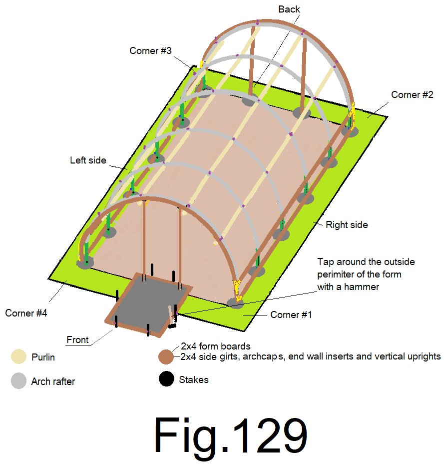
131) Use a framing hammer or similar sized hammer and gently tap the outside of the form boards, all the way around, to remove air and settle the cement. Fig129
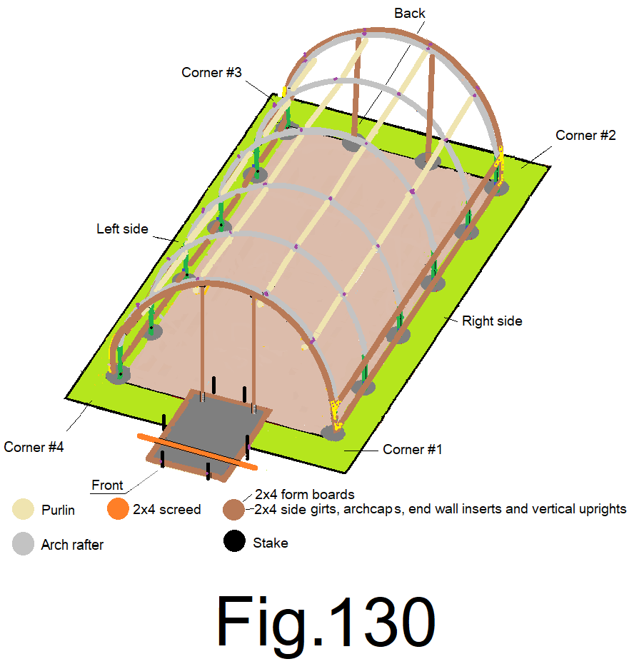
132) Use a 6 ft. long 2×4 “screed”, in order to screed your concrete, screed from front to back, up to the vertical 2×4’s, stop. Then, begin the screed on the other side of the vertical 2x4s until you reach the back form. Fig 130
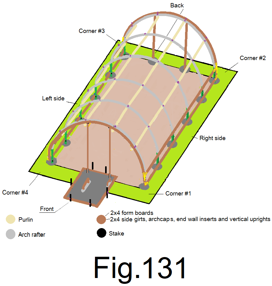
133) Use a concrete hand float to float the cement, use a concrete finishing edge tool and tool the edge around the perimeter. Fig 131
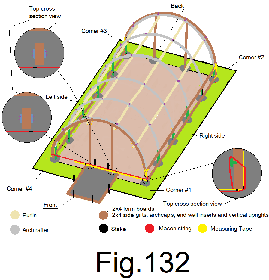
134) Re-attach the mason string from step 110), tightly, and add a carpenter pencil, as a spacer between the string and the sidewall corner insert at each end of the string. Measure from the outside edge of the 2×4 end wall corner insert, along the string; mark the string at 5 ft. 6 in. and at 8ft. 6in. and adjust the vertical 2x4s using the marks on the string as a reference, inside edge of the right side vertical 2×4 lined up to the 5 ft. 6 in. mark and the inside edge of the left side vertical 2×4 to the 8 ft. 6 in. mark and with a carpentry pencil sized gap between the string and each vertical 2×4. The metal straps will hold the vertical 2x4s in place because they are imbedded into the cement. You will need to check and re-set the vertical 2x4s as the cement sets up, and refloat and re-edge the cement as needed until cement is set. Fig. 132
Then, don’t delay
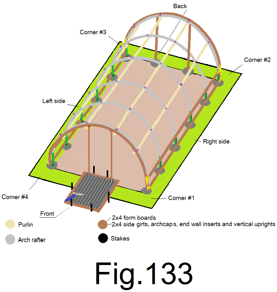
135) Remove the string, then use a kitchen broom or a “concrete finish broom” and put a broom finish on your landing from back to front, straight clean passes, one next to the other, smoothly passing by the vertical uprights without disturbing them. Let the concrete set up for a day. Fig 133
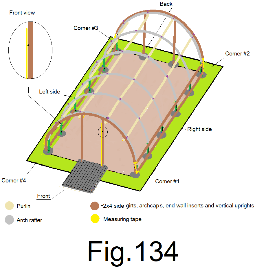
136) Remove the form boards and measure from the concrete landing up along the inside of the right side vertical 2×4 up to 6 ft. 8 in. or 80 in. and mark the front inside edge. Fig 134
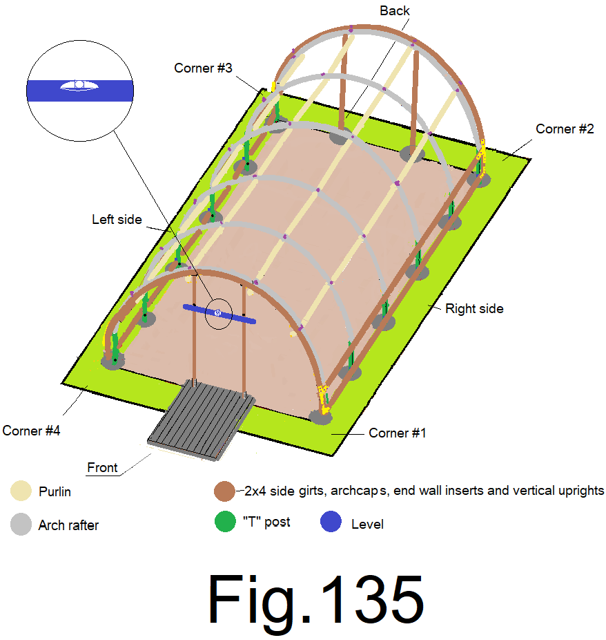
137) Use a 4 ft. or longer level and mark level on the front inside edge of the other vertical 2×4. Fig 135
138) Use a speed square and make a cross mark on the inside of both vertical 2x4s, at the 6’8” marks. Fig136
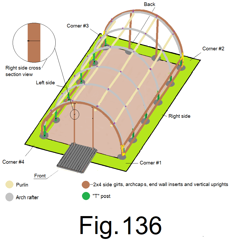
139) Using vise grip “C” clamps, clamp both vertical 2x4s just below the cross marks and at the center of the vertical 2x4s. Fig 137
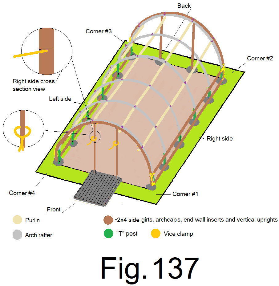
140) Cross cut a 2×4 at 3 ft. Using 3 in. wood screws to attach the 3 ft. 2×4 between the vertical 2x4s, on top of the clamps, each end of the 3 ft. 2×4’s bottom edge set to the cross mark on the vertical 2x4s and the front edges of all framing flush. Fig 138
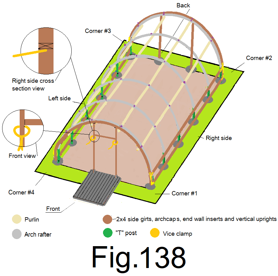
The concrete landing is at the entrance. The two vertical 2x4s and the horizontal 2×4 make up the door frame and where the entrance door will be hung. The two vertical 2x4s need to be relatively straight and plumb.
141) Re-attach the mason string from step 122), tightly, without any spacers. Mark the outside of both vertical 2x4s at the mason string. Fig 139
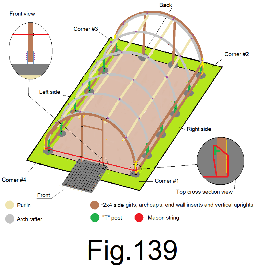
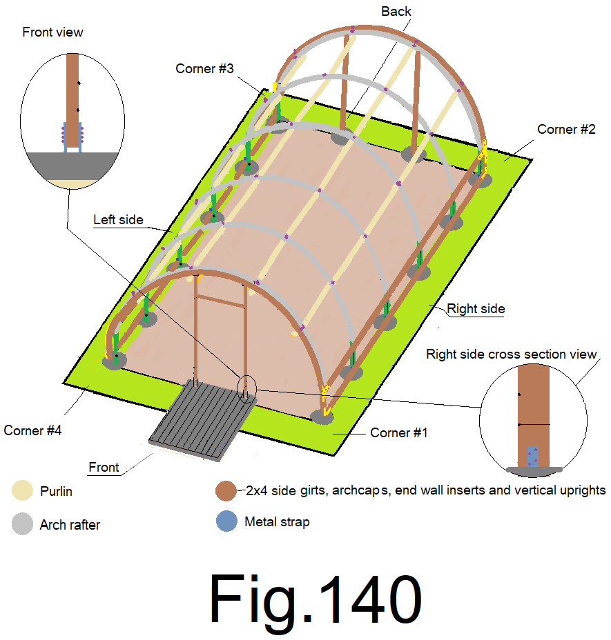
142) Remove the mason string, measure down 31/2 in. from the mark at the outside of the both vertical 2x4s and make 2 new bottom marks. Using a speed square, cross mark the outside of both vertical 2x4s at the new bottom marks. Fig 140
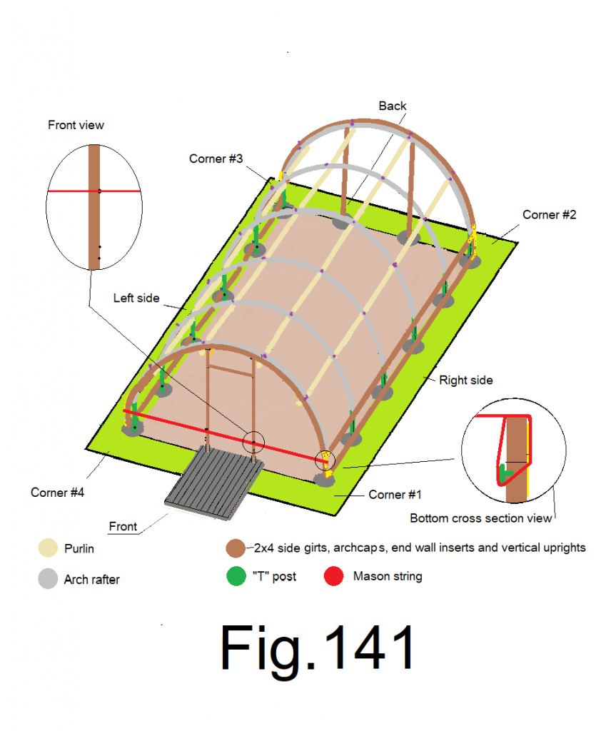
143) Attach the mason string to the top of the sidewall 2×4 corner inserts on both sides, oriented to the outside and attached tightly without any spacers. Mark the outside of both vertical 2x4s at the mason string. Fig 141
144) Remove the mason string.
145) Use a speed square to cross mark the 2) top marks along the outside of both vertical 2x4s.
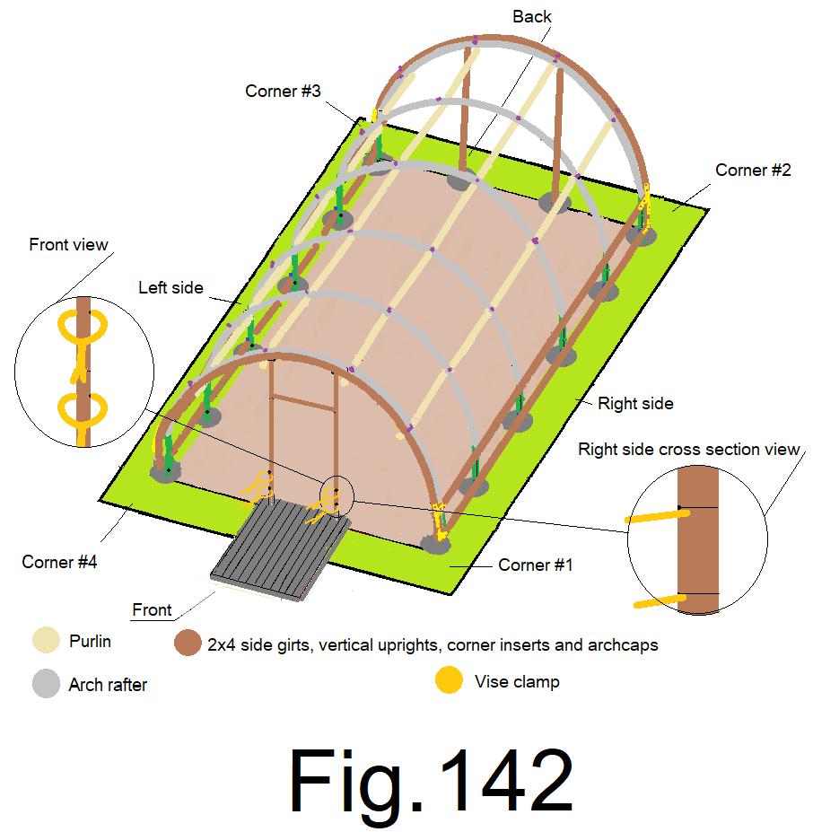
146) Using 4 vise grip “C” clamps, clamp both vertical 2x4s, just below the top and bottom cross marks and at ¾ in. in from the front edge. Fig 142
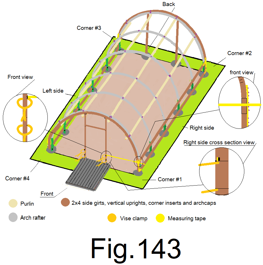
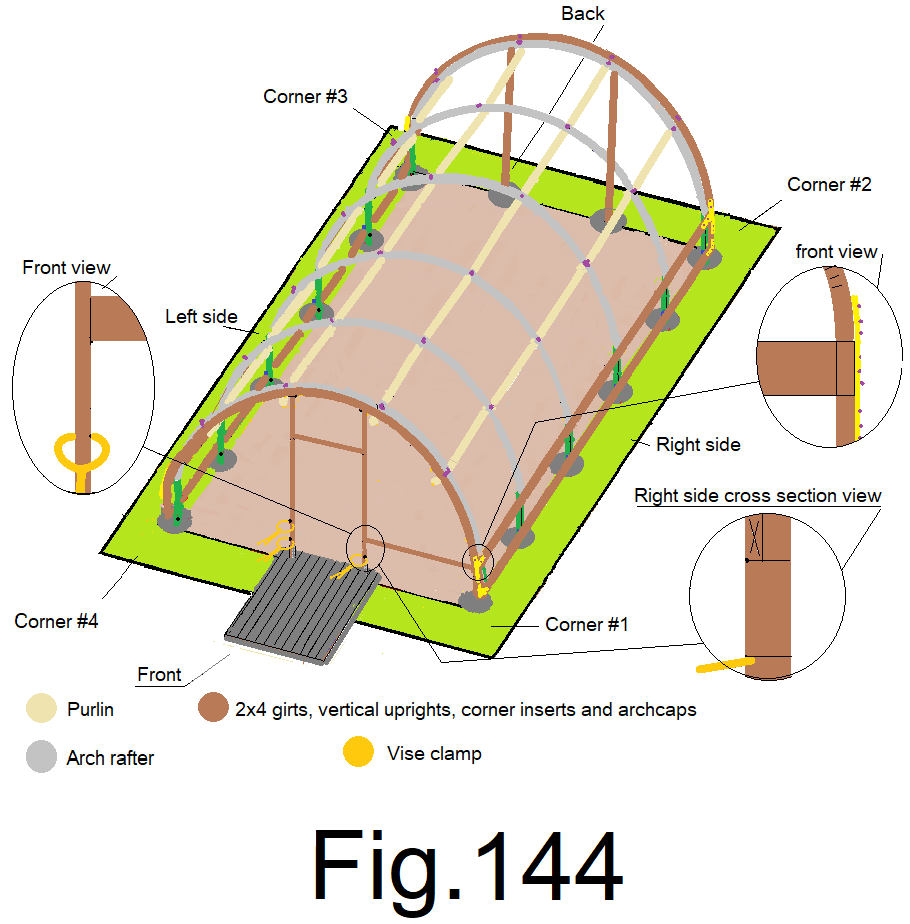
147) Measure between the right side vertical 2×4, just above the top right clamp, over to the corresponding inside edge of the right sidewall girt. Fig 143
148) Cut a 2×4 front top girt at the number from step 147). Place one end of the 2×4 front right top girt on top of the clamp and cross mark on the 2×4 vertical upright. Attach the other end of the 2×4 front top girt to the inside of the right side top girt at the front using 3 in. wood screws. Secure the 2×4, right front girt, to the 2×4 vertical upright, with 3 in. wood screws and remove the clamp. Fig 144
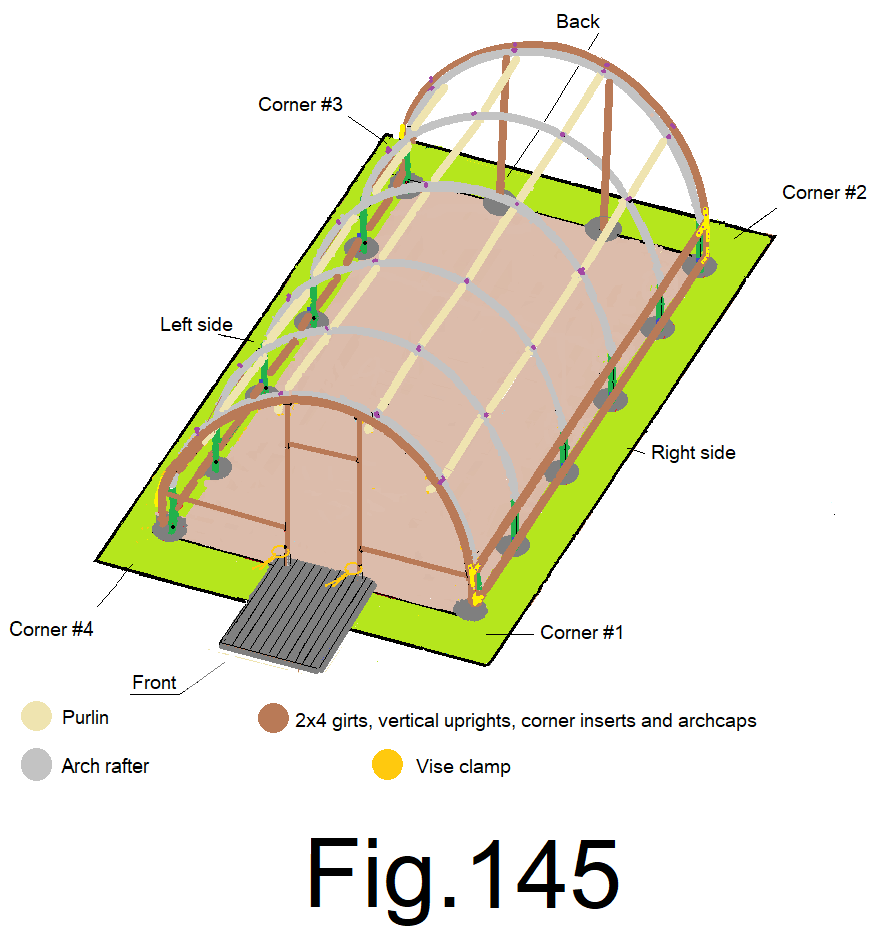
149) Repeat steps 147) and 148) for the left front top girt. Fig 145
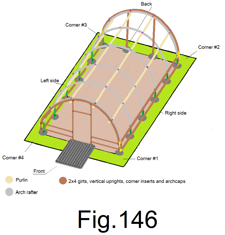
150) Repeat steps 147) and 148) for both front bottom girts. Fig146
© 2021