Greenhouse construction tutorial. How to JDPShack. Directions part 1.
John Pandrea
ALWAYS WEAR SAFETY GLASSES, EAR PROTECTION, WORK GLOVES WHEN HANDLING METEL AND A DUST MASK WHEN DIGGING HOLES, MIXING CEMENT and CUTTING or DRILLING.
How to JDPShack
Steps 151-200
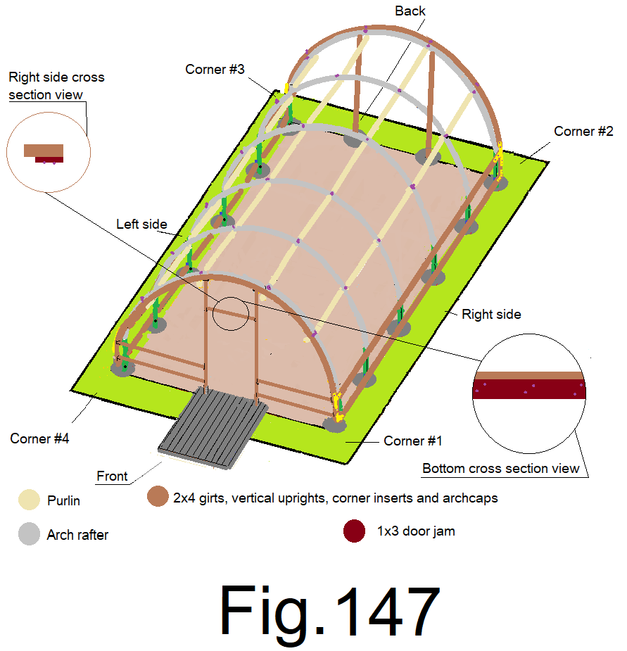
151) Cross cut a 1×3 at 36 in. Use 2 vise grip “C” clamps to clamp the 36 in. 1×3 to the bottom of the top door frame flush to the back edge of the top door frame. Secure with 2 in. wood screws. Fig147
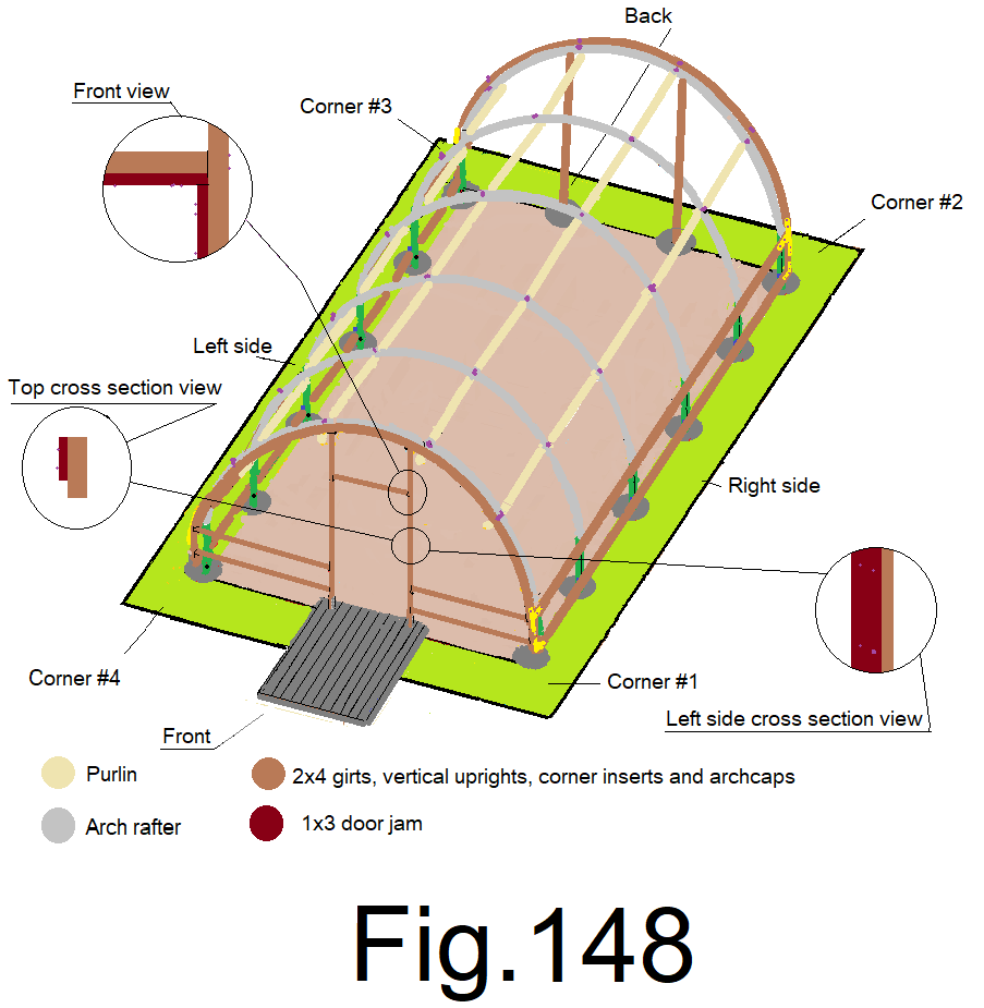
152) Cross cut a 1×3 at 78 in. Use 2 vise grip “C” clamps to clamp the 78 in. 1×3 to the inside of the right side door frame, tight to the top and flush to the back edge of the door frame. Secure with 2 in. wood screws. Fig 148
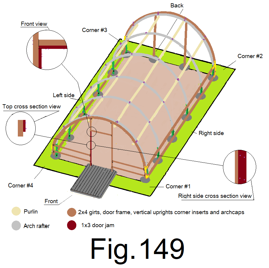
153) Cross cut a 1×3 at 78 in. Use 2 vise grip “C” clamps to clamp the 78 in. 1×3 to the inside of the left side door frame, tight to the top and flush to the back edge of the door frame. Secure with 2 in. wood screws. Fig 149
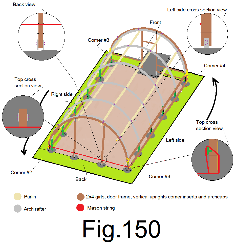
154) Attach a mason string to the bottom of the back right side wall corner 2×4 insert, with the string oriented to the outside, extend the string to the bottom of the back left side wall corner 2×4 insert and tightly secure it. Mark both middle vertical 2x4s on the back at the string on both sides of the vertical 2x4s. Measure down 3 ½ in. from each mark and make a new mark. Cross mark all 4 new lower marks with a speed square. Fig150
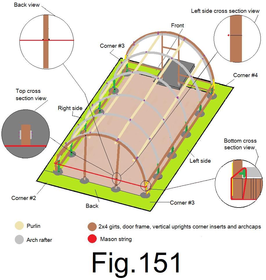
155) Take down the mason string and attach it to the top of the right side wall back corner insert, with the string oriented to the outside. Extend the string to the top of the left side wall back corner insert and tightly secure it. Mark both vertical 2x4s on the back, at the string, on both sides of each vertical 2×4. Cross mark all 4 upper marks with a speed square. Fig 151
156) Use 4) vise grip “C” clamps. Clamp the vertical 2x4s just below all 8) cross marks, 3/4 in. from the outside edge. Fig 152
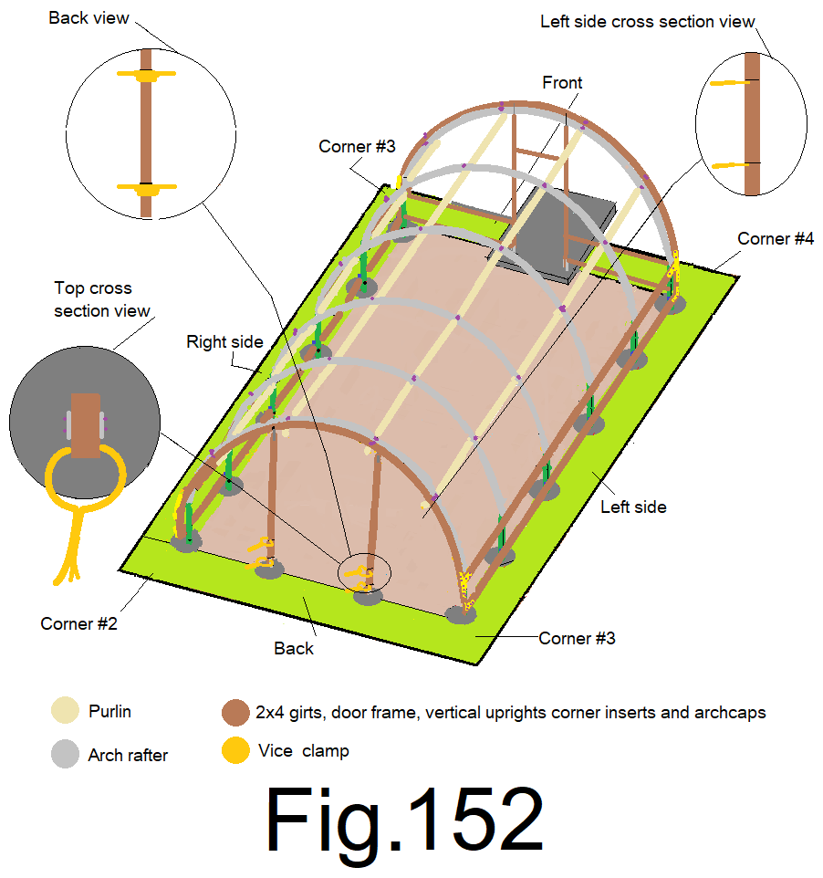
Use these clamps to assist in holding up the back girts as you install them.
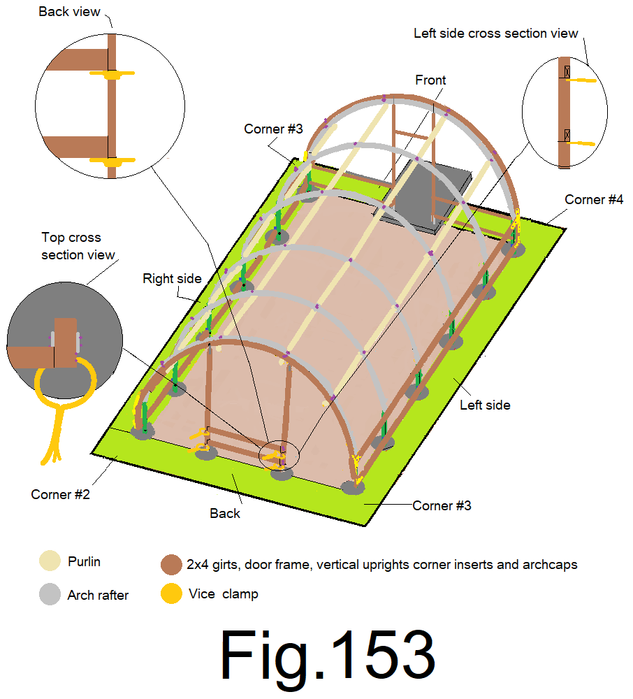
157) Measure between the back vertical 2x4s at the upper cross marks, just above the clamps, cross cut a 2×4 “back top center girt” at that number. Install the 2×4 back top center girt between the vertical 2x4s just above the upper cross marks and attach with 3 in. wood screws. Repeat between the back vertical 2x4s lower girt marks. Fig 153
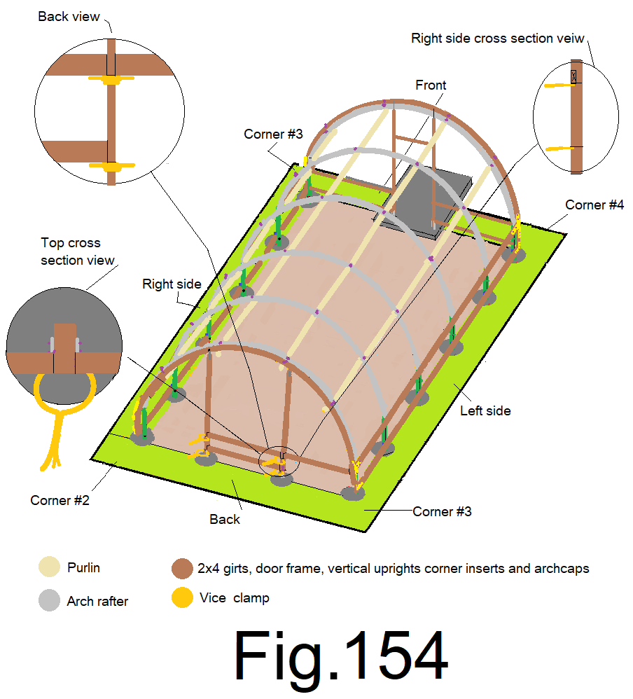
158) Measure from the back wall left 2×4 vertical upright at the left side top cross mark, just above the clamp, over to the left side wall top girt inside edge. Crosscut a 2×4 at that number and install the 2×4 back wall top left girt and attach it with 3 in. wood screws. Fig 154
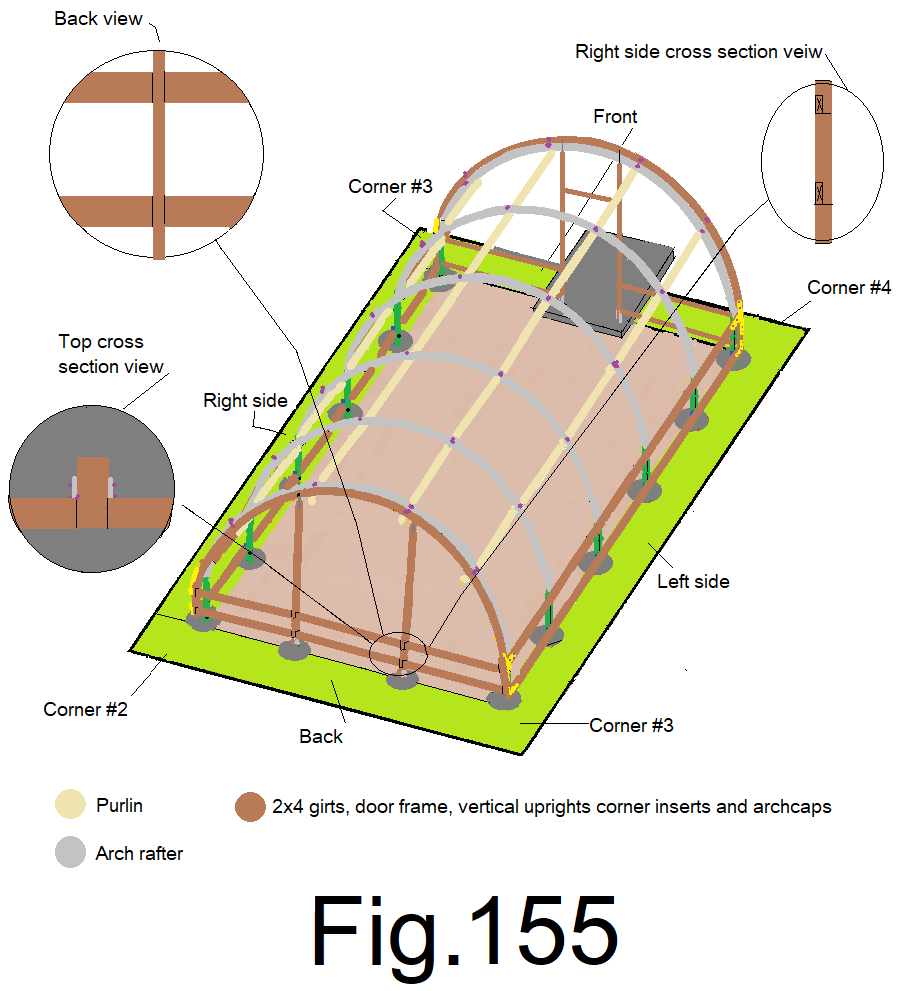
159) Repeat step 158), at the other 3) back girt locations. Then remove the clamps. Fig 155
160) Un-roll 60 in. wide bug screen on the ground across the back wall. Use a T-50 stapler with ½ in stainless steel staples and attach the top of the leading edge of the screen, to the top of the back left corner where the top back girt and top side girt meet, while holding the top of the screen 1 in. above the back top girt. And, leave an extra 6 in. of additional screen beyond the corner. Fig. 156
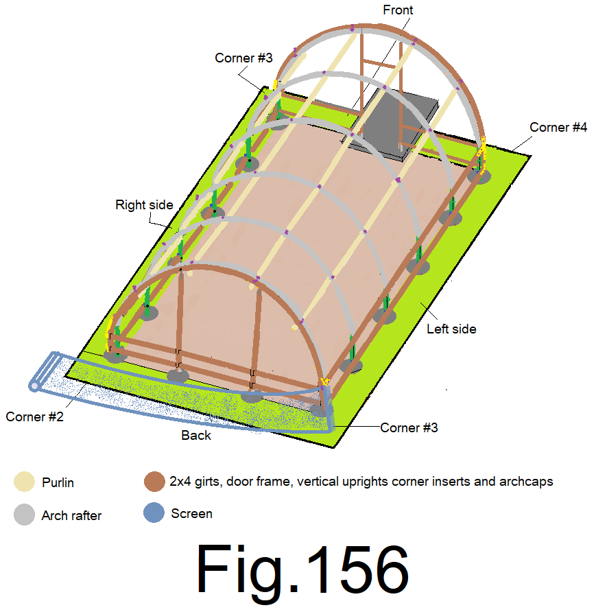
161) Un-roll enough screen beyond the back right corner and staple the top of the screen to the right side top back girt where the top back girt and top right side girt meet, while holding the top of the screen 1 in. above the top edge of the top back girt. Do not pull the screen tight; leave enough slack so that the screen sags in the middle about 1 ft. Fig 157
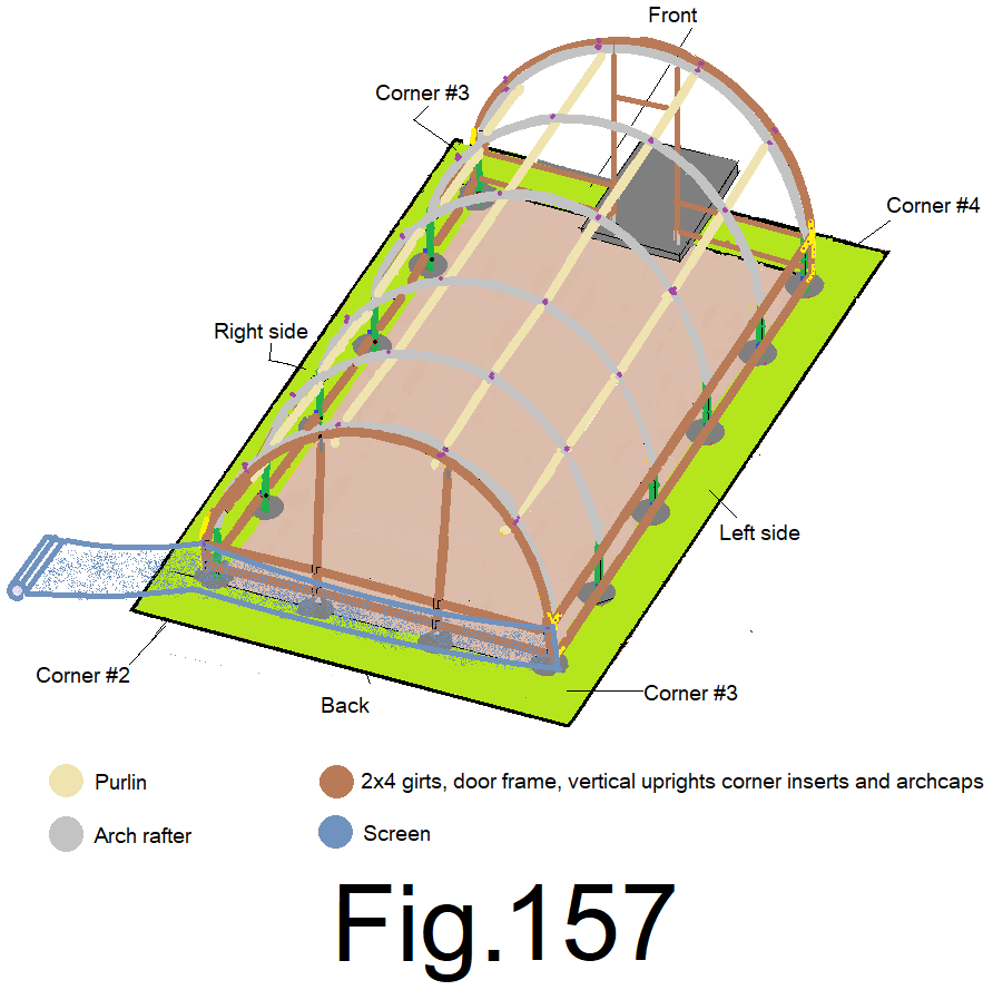
162) At the center of the back wall, pull the screen straight up and staple it to the top girt while holding the screen centered end to end and 1 in. above the top girt. Fig 158
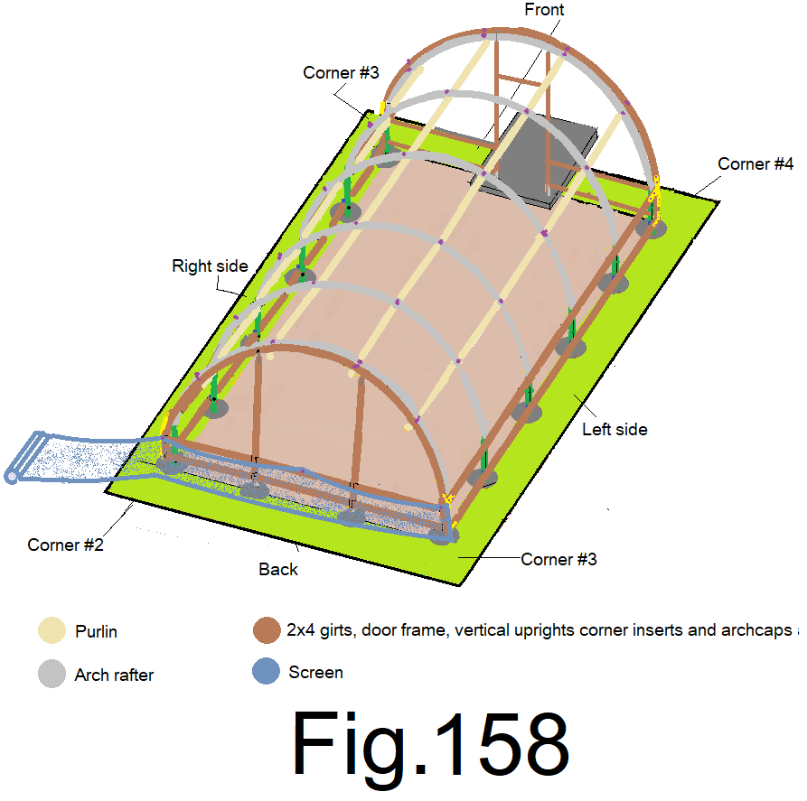
163) At the quarters of the back wall, pull the screen straight up and staple it to the top girt while holding the screen 1 in above the top girt. (2 locations). Fig 159
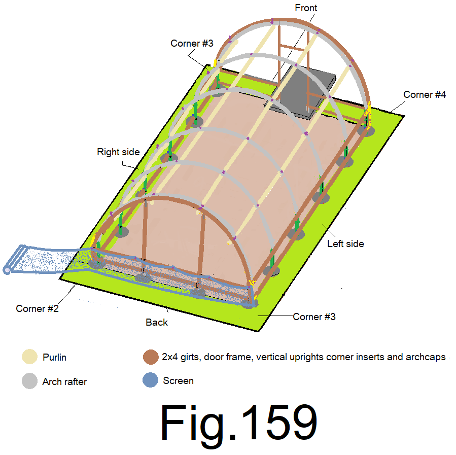
164) At the eighths of the back wall, pull the screen straight up and staple it to the top girt while holding the screen 1 in. above the top girt. (4 locations) Fig 160
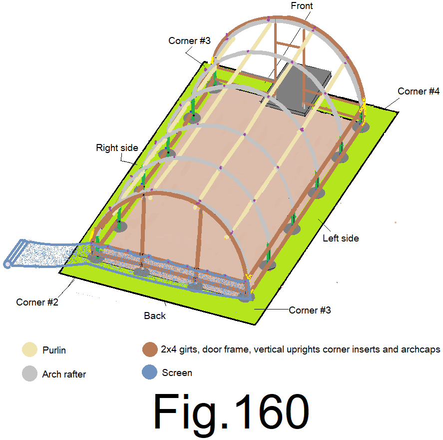
165) At the sixteenths of the back wall, pull the screen straight up and staple it to the top girt while holding the screen 1 in. above the top girt. (8 locations) Fig 161
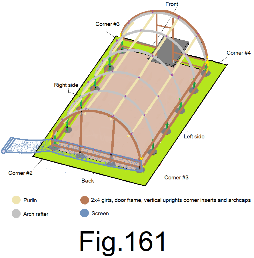
166) At the center of the back wall, slightly tension the screen straight down and staple it to the bottom girt. Let the extra screen fold at the ground and lay on the ground. Fig 162
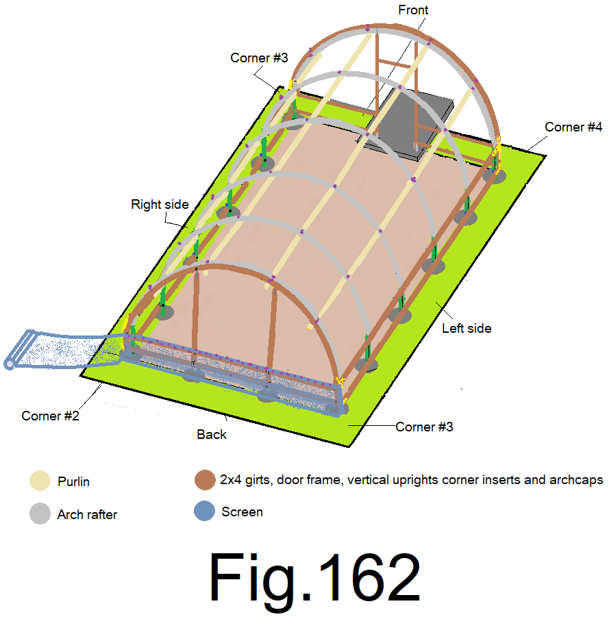
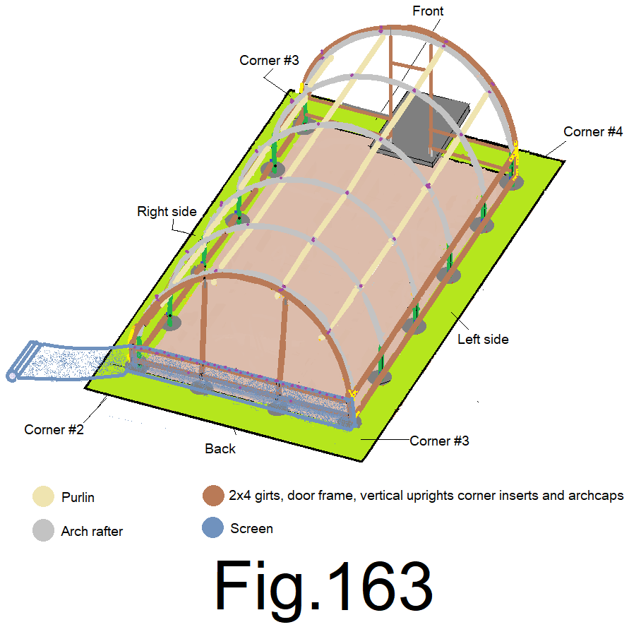
167) At the quarters of the back wall, slightly tension the screen straight down and staple it to the bottom girt. (2 locations). Let the extra screen fold at the ground and lay on the ground. Fig 163
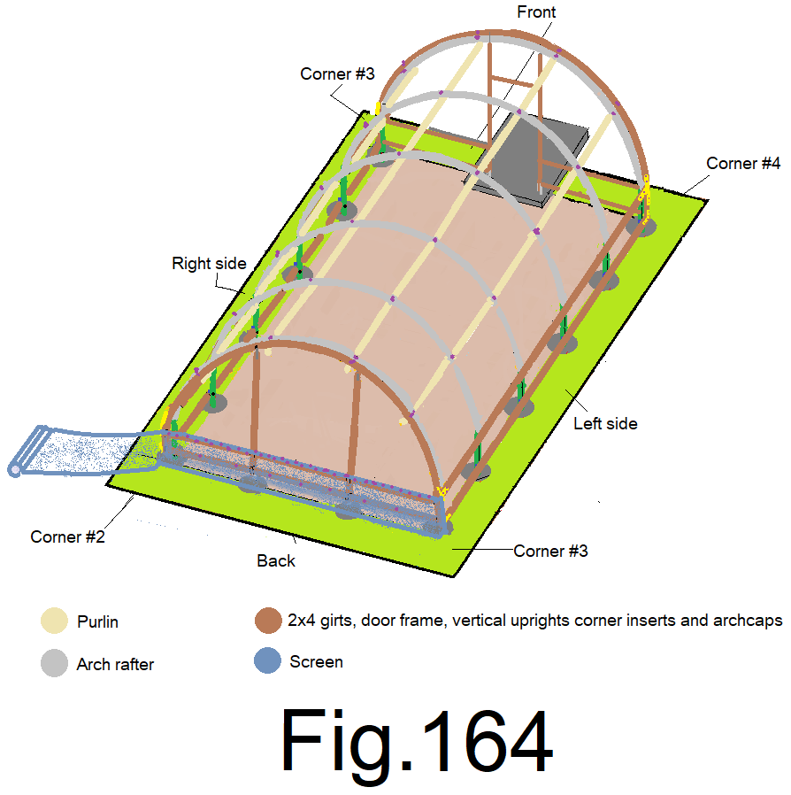
168) At the eighths of the back wall, slightly tension the screen straight down and staple it to the bottom girt. (4 locations). Let the extra screen fold at the ground and lay on the ground. Fig 164
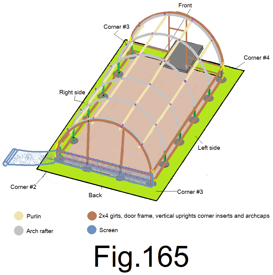
169) At the sixteenths of the back wall, slightly tension the screen straight down and staple it to the bottom girt. (8 locations). Let the extra screen fold at the ground and lay on the ground. Fig 165
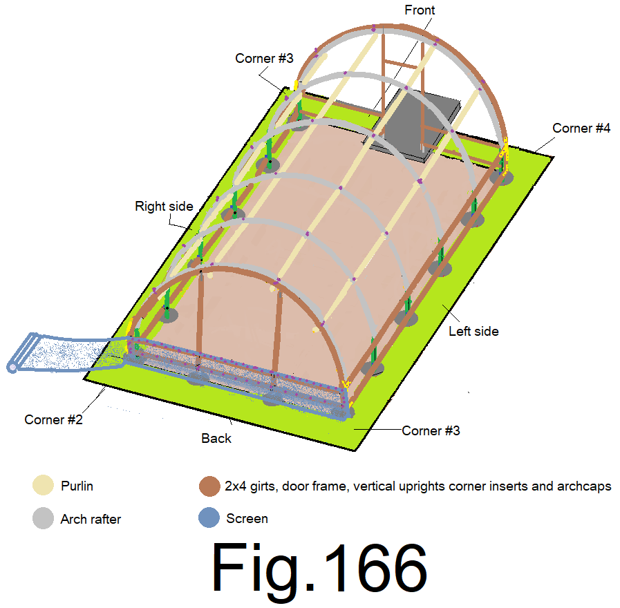
170) At the back corners, slightly tension the screen straight down and staple it to the bottom girt. Staple the screen to the back edge of the side wall corner insert. Let the extra screen fold at the ground and lay on the ground. Fig 166
171) Un-roll the screen, around the back corner and along the side wall beyond the front corner. Fig 167
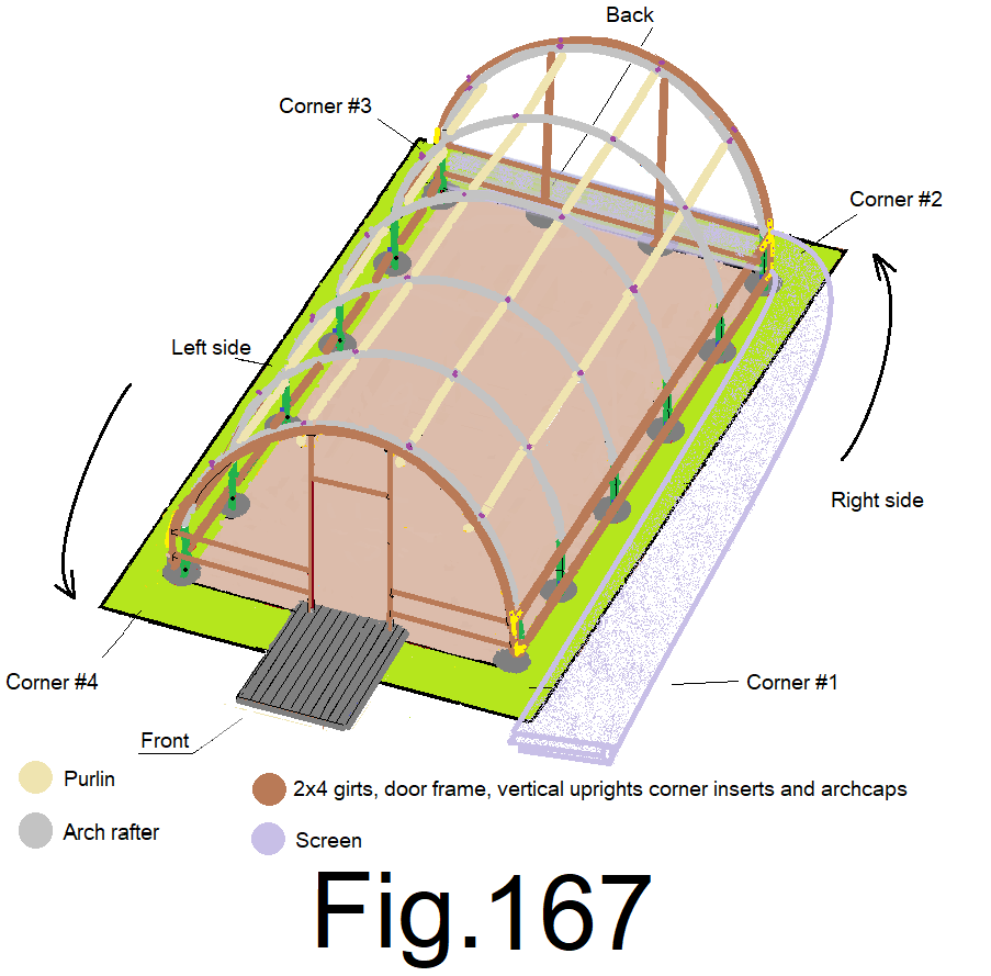
172) Staple the screen to the sidewall top girt at the back right corner while holding the top of the screen 1 in. above the top of the top girt. Fig 168
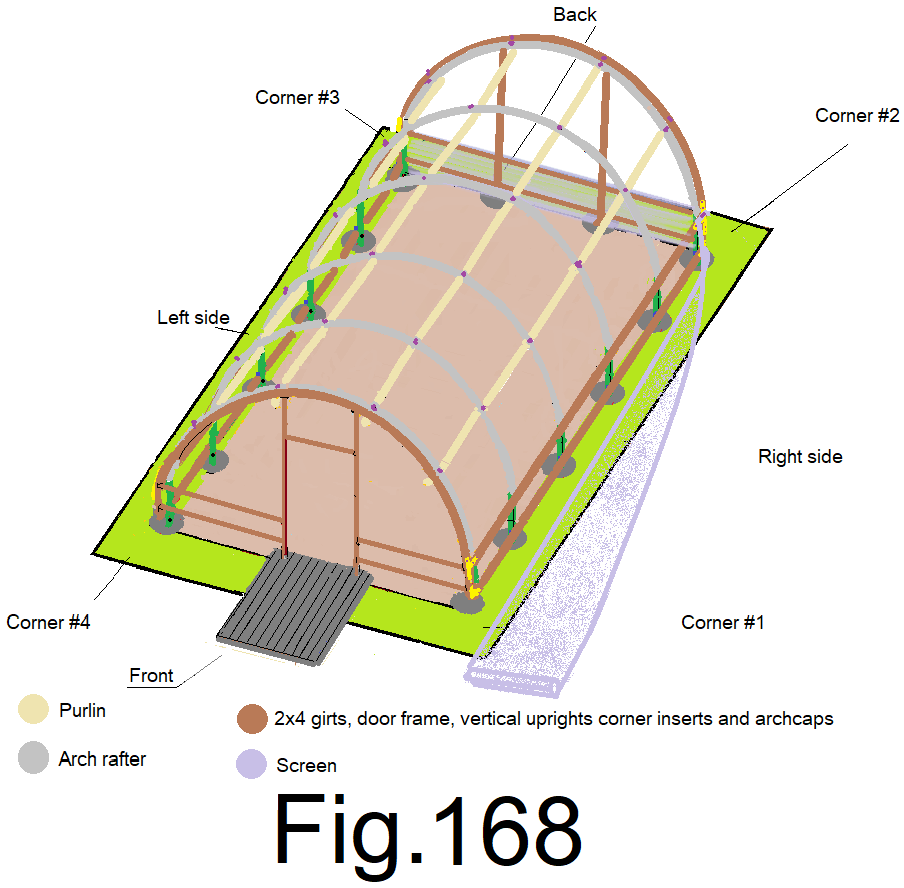
173) Staple the screen to the sidewall top girt at the front right corner while holding the screen 1 in. above the top pf the top girt, not to tight, leave enough slack so that the screen sags about 16 in. at the center. Fig 169
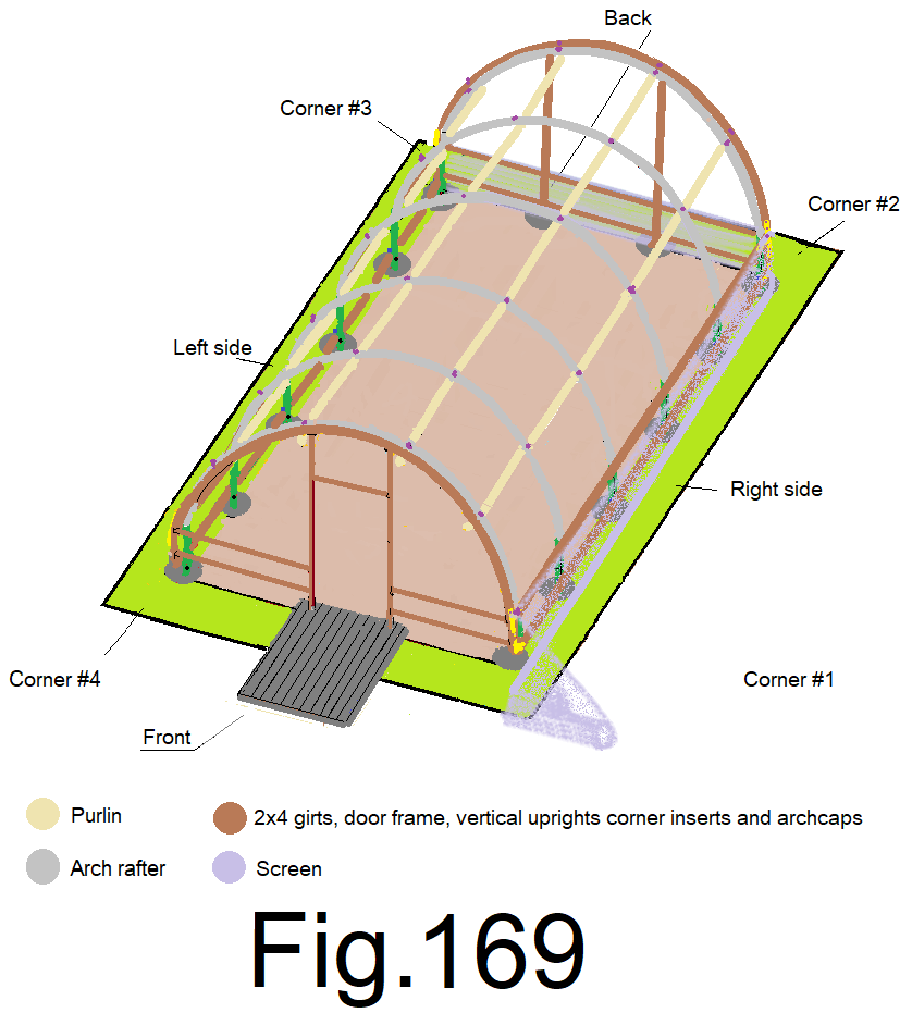
174) At the center of the side wall, pull the screen straight up and staple it to the top girt while holding the screen 1 in. above the top girt. Fig 170
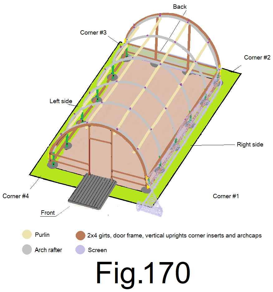
175) At the quarters of the side wall, pull the screen straight up and staple it to the top girt while holding the screen 1 in. above the top girt. (2 locations). Fig 171
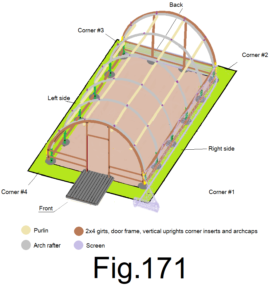
176) At the eighths of the side wall, pull the screen straight up and staple it to the top girt while holding the screen 1 in. above the top girt. (4 locations). Fig 172
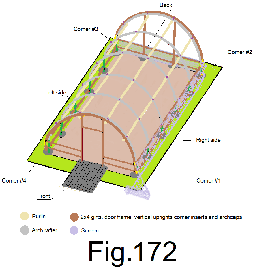
177) At the sixteenths of the sidewall, pull the screen straight up and staple it to the top girt while holding the screen 1 in. above the top girt. (8 locations). Fig 173
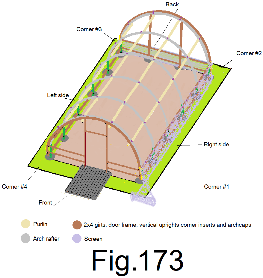
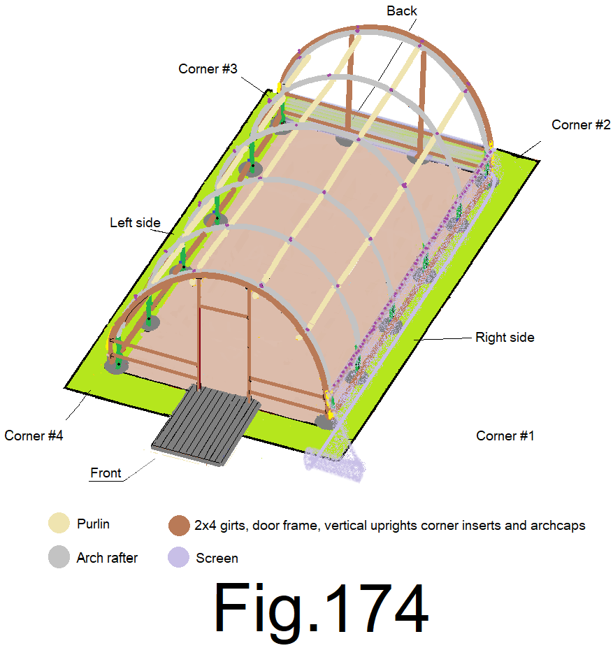
178) At the thirtyseconds of the sidewall, pull the screen straight up and staple it to the top girt while holding the screen 1 in. above the top girt. (16 locations). Fig 174
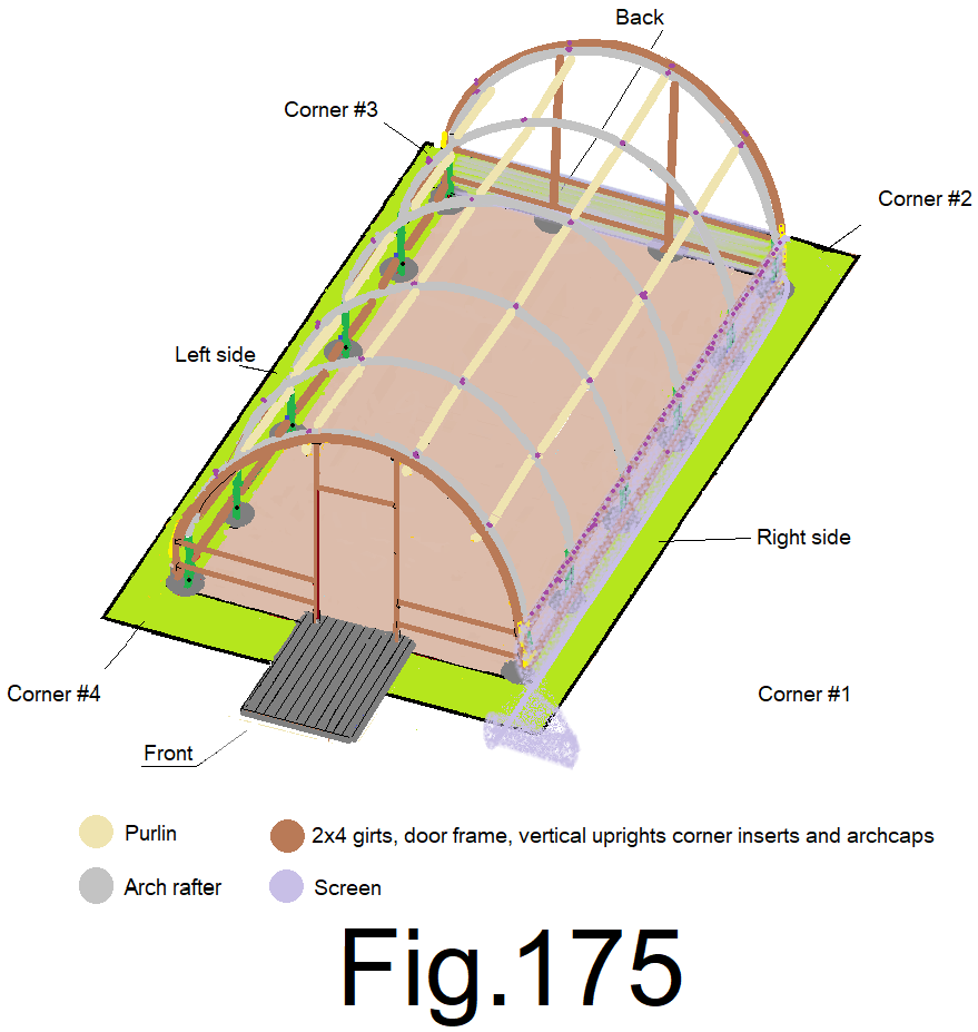
179) At the center of the side wall, slightly tension the screen straight down and staple it to the bottom girt. Let the extra screen fold at the ground and lay on the ground. Fig175
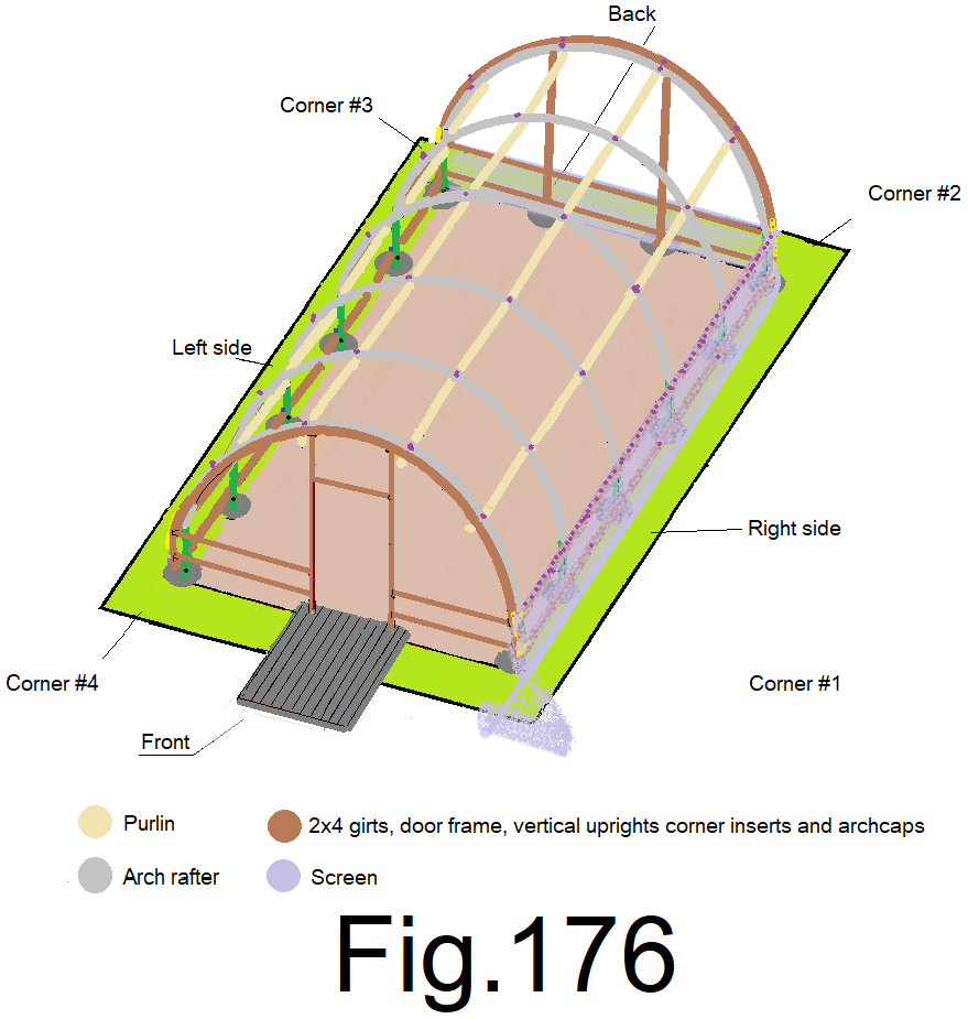
180) At the quarters of the side wall, slightly tension the screen straight down and staple it to the bottom girt. (2 locations) Fig176
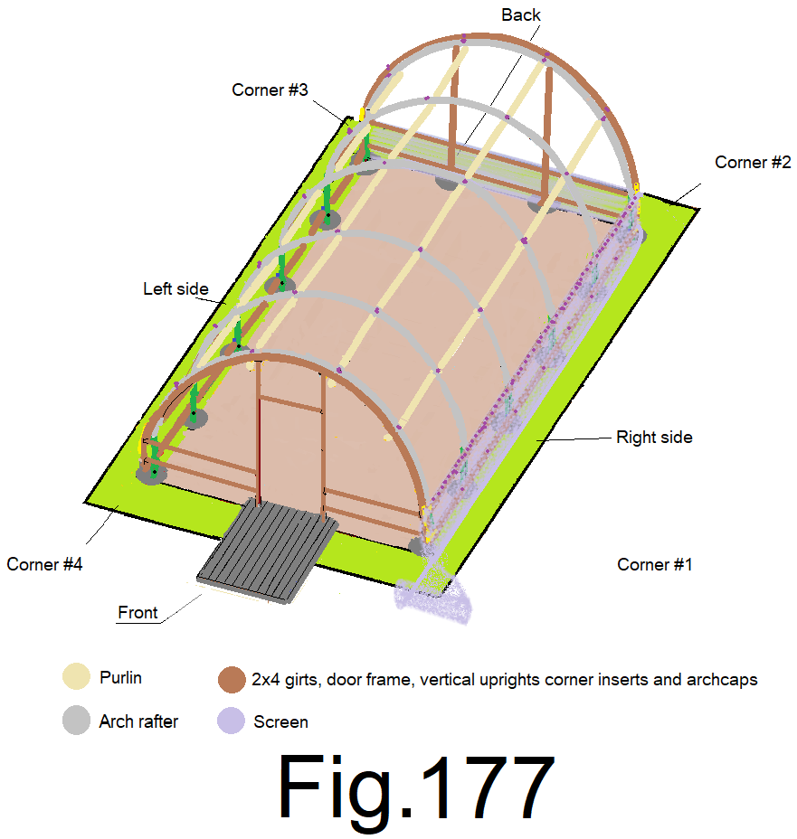
181) At the eighths of the side wall, slightly tension the screen straight down and staple it to the bottom girt. (4 locations) Fig177
182) At the sixteenths of the side wall, slightly tension the screen straight down and staple it to the bottom girt. (8 locations) Fig178

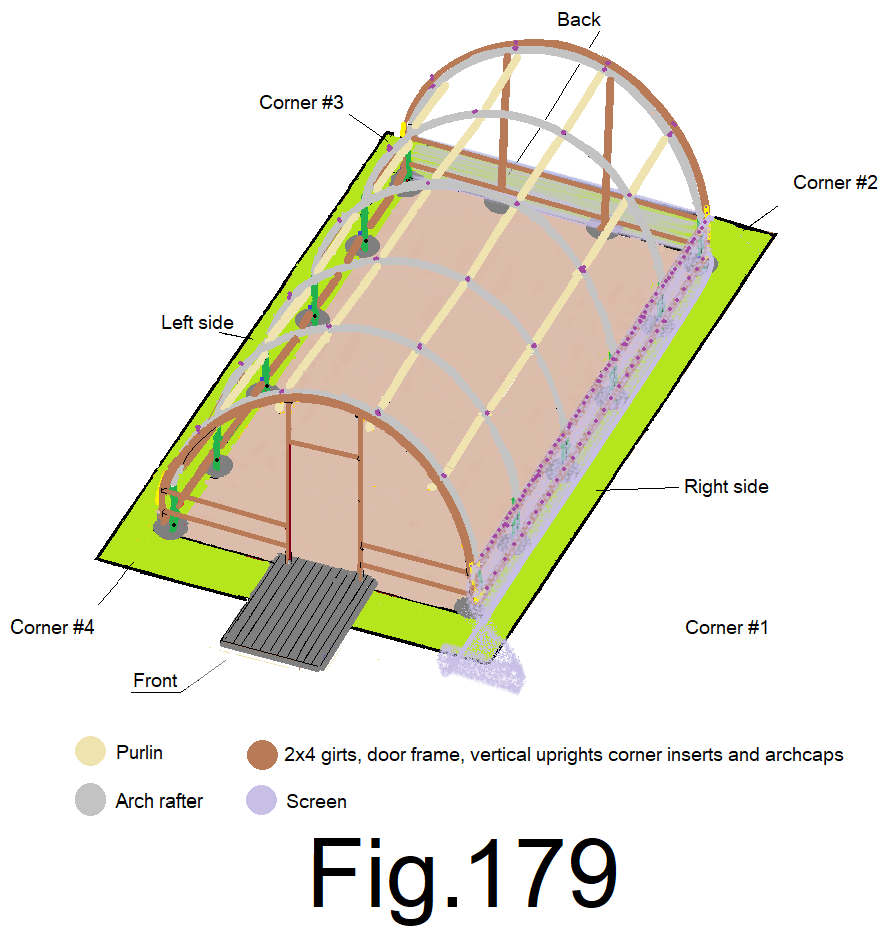
183) At the thirtyseconds of the side wall, slightly tension the screen straight down and staple it to the bottom girt. (16 locations) Fig 179
184) At the outside corners, slightly tension the screen straight down and staple it to the bottom sidewall girt. Staple the screen to the corner insert. Fig 180
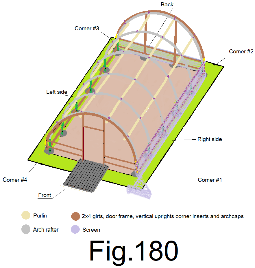
185) Un roll the screen, around the right front corner and along the front wall beyond the left front corner. Fig181
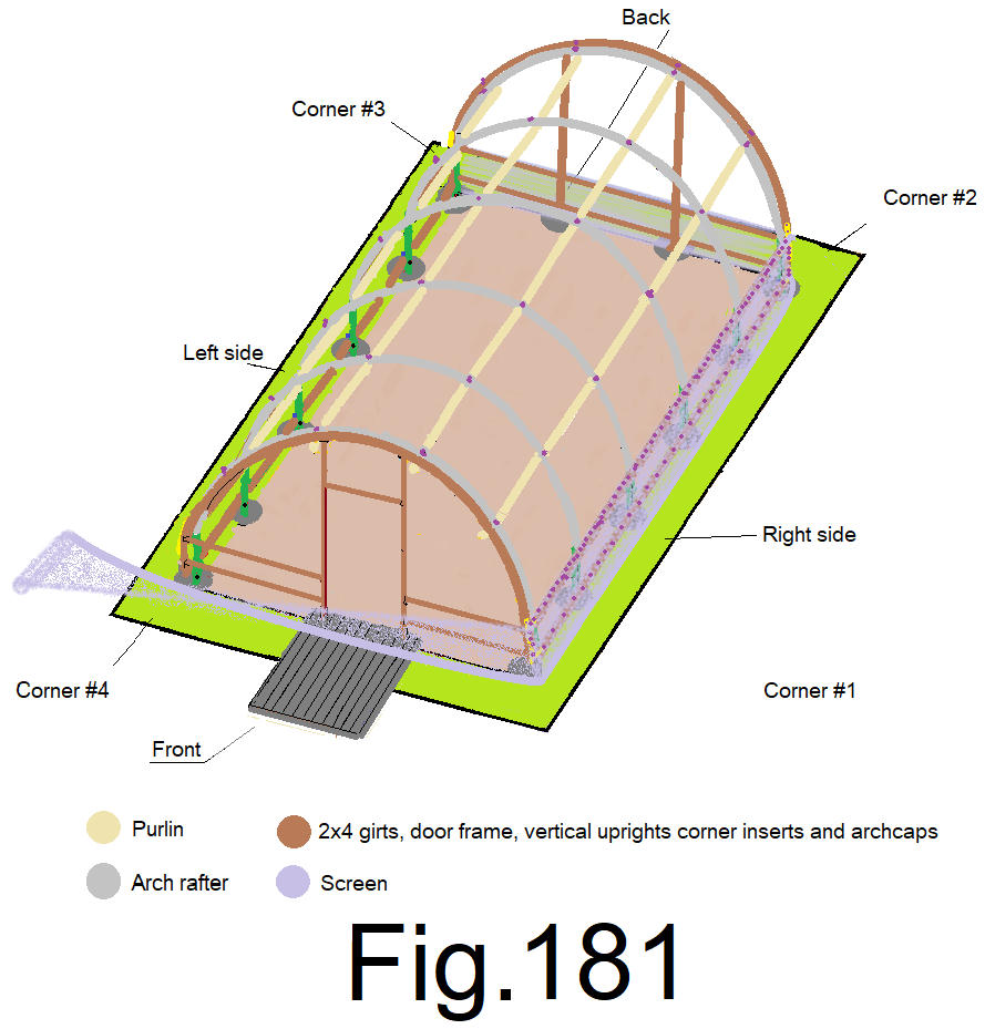
186) Staple the screen to the front wall top girt at the front right corner, while holding the top of the screen 1 in. above the top girt. Fig182
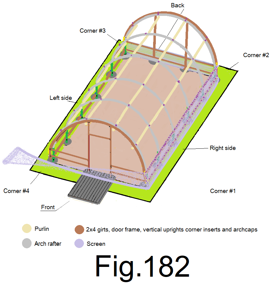
187) Staple the top of the screen to the front left corner while holding the top of the screen 1 in. above the top girt. Do not pull the screen tight; leave enough slack so that the screen sags in the middle about 1 ft. Fig 183
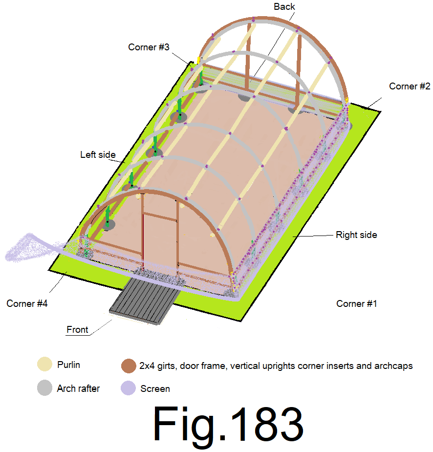
188) At the offset center of the front wall, at the right side of the door frame, pull the screen straight up and staple it to the top girt while holding the screen centered end to end and 1 in. above the top girt. Repeat at the other side of the door. Fig 184
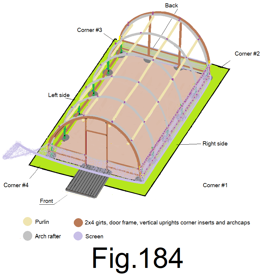
189) At the quarters of the front wall, pull the screen straight up and staple it to the top girt while holding the screen 1 in. above the top girt. (2 locations). Fig 185
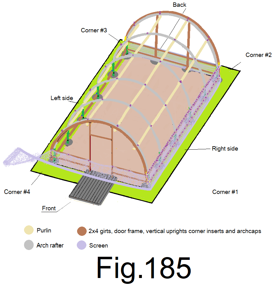
190) At the eighths of the front wall, pull the screen straight up and staple it to the top girt while holding the screen 1 in. above the top girt. (4 locations) Fig 186
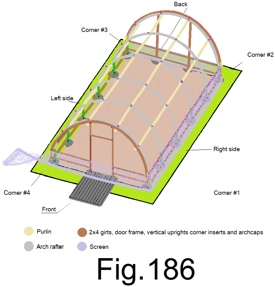
191) At the sixteenths of the front wall, pull the screen straight up and staple it to the top girt while holding the screen 1 in. above the top girt. (8 locations) Fig 187
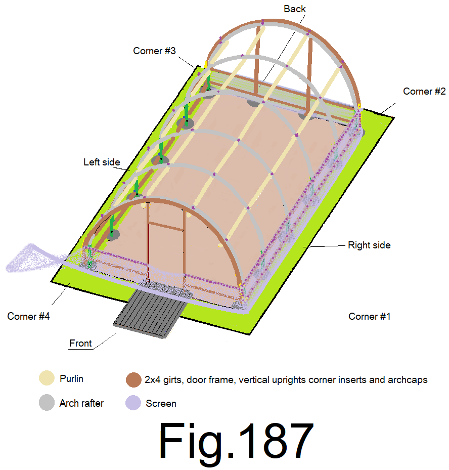
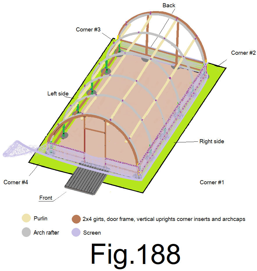
192) At the offset center of the front wall, slightly tension the screen straight down along the door frame and staple it to the bottom girt. Let the extra screen fold at the ground and lay on the ground. Repeat at the other side of the door frame. Fig 188
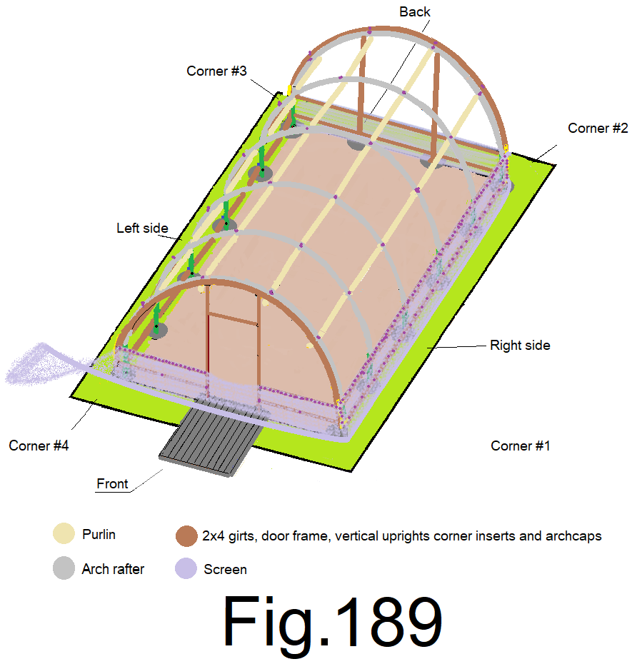
193) At the quarters of the front wall, slightly tension the screen straight down and staple it to the bottom girt. (2 locations) Fig 189
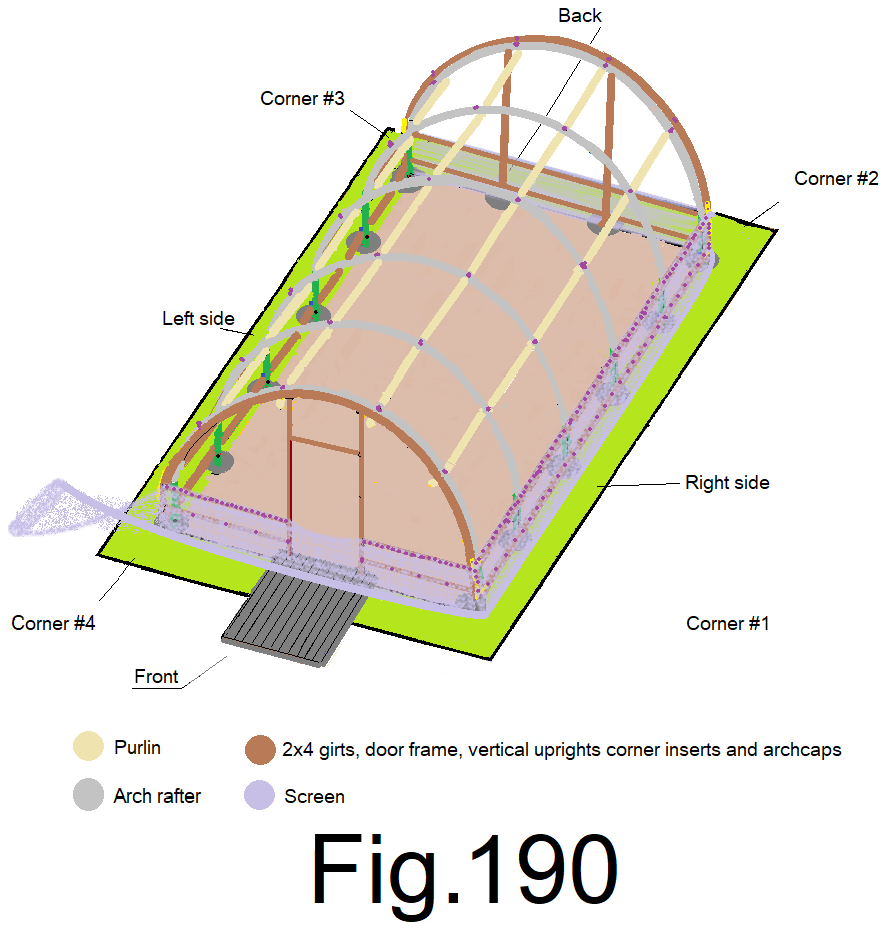
194) At the eighths of the front wall, slightly tension the screen straight down and staple it to the bottom girt. (4 locations) Fig 190
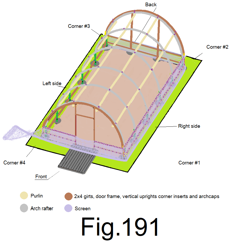
195) At the sixteenths of the front wall, slightly tension the screen straight down and staple it to the bottom girt. (8 locations) Fig191
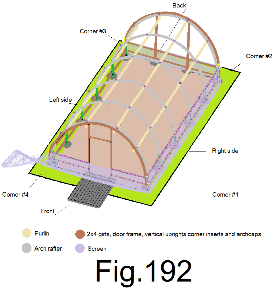
196) At the outside corners, slightly tension the screen straight down and staple it to the bottom girt. Staple the screen every 4 in. at both sides at the corner inserts. Fig 192
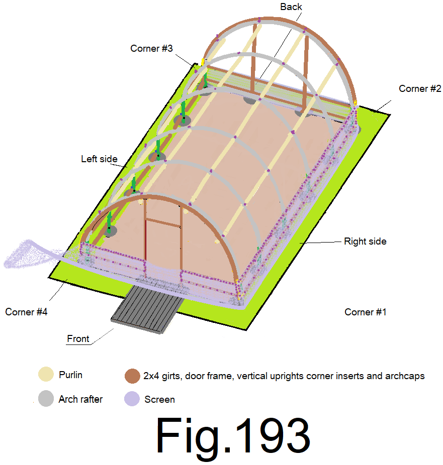
197) Staple the screen to both of the side door frames, every 4 in. Fig 193
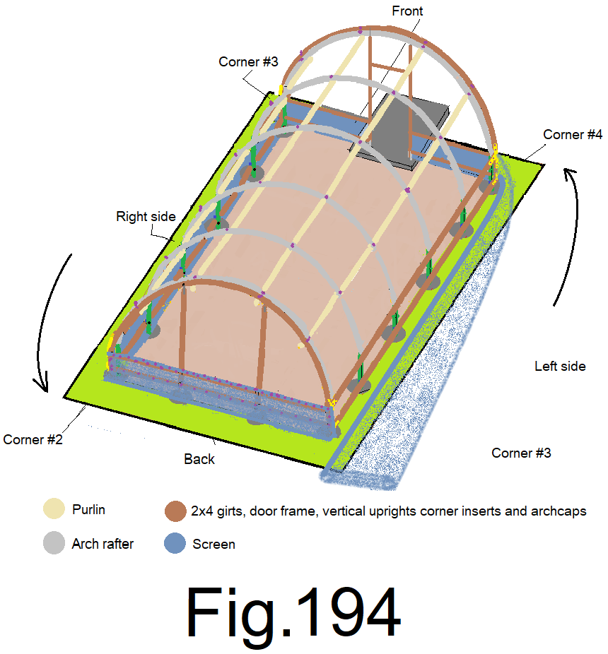
198) Un roll the screen, around the front left corner and along the left side wall beyond the back left corner. Fig 194
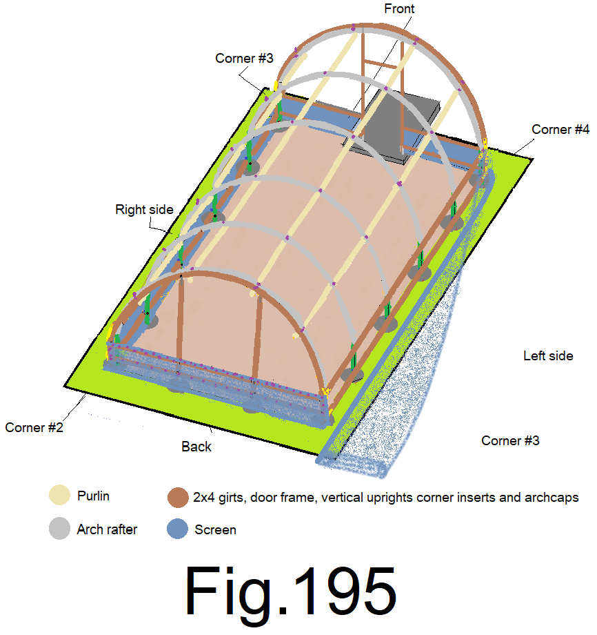
199) Staple the screen to the left sidewall top girt at the front left corner, while holding the top edge of the screen one in. above the top girt. Fig 195
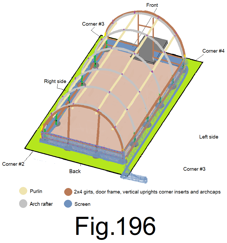
200) Staple the screen to the left sidewall top girt at the left back corner, with top edge 1 in. above the top girt, not to tight, leave enough slack so that the screen sags about 16 in. at the center. Fig 196
© 2021